
1 Numbers in Computing
Mathematics is the most beautiful and most
powerful creation of the human spirit.Stefan Banach
Computer processors might be perceived as extremely efficient “number crunchers” which means that they process enormous streams of information expressed only with numbers. It is worth for engineers to understand various ways by which electronic systems process these numbers.
Humans in almost every corner of the earth are used to decimal system. This is so easy and natural to count with fingers hence positional system based on powers of tens is the most common nowadays. It is well known in practice but revising it might be helpful in understanding other systems discussed here. Look at the example:
[latex]40375 = 4\times10^4 + 0\times10^3 + 3\times10^2 + 7\times10^1 + 5\times10^0 = 40000 + 0 + 300 + 70 + 5[/latex]
In computer systems decimal numbers usually have no prefix or suffix but sometimes they are suffixed with “d”: [latex]40375d[/latex].
Binary System
Computers do not use decimal system. They are working on bits where bit is unit of information. It can have only one of two possible but different values such as:
| True | False |
|---|---|
| 1 | 0 |
| Day | Night |
Binary system has only two digits: 0 and 1. It is also positional as decimal system, but the base equals 2 (that is number of digits). Binary numers sometimes are suffixed with letter “b” or prefixed with “0b”. In the following example every multiplicand is expressed in decimal mode but it was omitted to simplify the equation and make it easier to follow the process:
[latex]0b1011 = 1\times2^3 + 0\times2^2 + 1\times2^1 + 1\times2^0 = 1\times8 + 0\times4 + 1\times2 + 1\times1 = 8d + 2d + 1d = 11d[/latex]
Above example also shows how binary number is converted to decimal mode. The series of multiplicands (starting from the rightmost position) in this conversion is easy to understand, reproduce or even remember: 1, 2, 4, 8, 16, 32, 64, 128, 256, 512, 1024, 2048, 4096, 8129, 16384, 32768, 65536, …
Conversion in from decimal mode to binary is a bit more tricky and there are several ways to do it. First approach is repetitive division by 2 with remainder that indicates value of bit at specific position. Example:
[latex]\begin{aligned} 11d = 2\times5d + 1\\ 5d = 2\times2d + 1\\ 2d = 2\times1d + 0\\ 1d = 2\times0d + 1\end{aligned}[/latex]
If we write remainders starting from the last one we will get binary value: 1011b.
The above method works well for any value. But for small values simpler method might be employed which is based on subtraction. However, it requires to know (e.g. remember) weights at different digit positions. In every step a biggest possible weight is subtracted from the number that is being converted provided that result will remain positive number. At positions with corresponding weights “ones” are set leaving all other positions with “zeros”. Example:
[latex]\begin{aligned} 11d - 8d &= 3d \qquad\text{8d subtracted successfully so there should be ``1''}\\ 3d - 0d &= 3d \qquad\text{4d cannot be subtracted within positive integers so ``0''}\\ 3d - 2d &= 1d \qquad\text{2d subtracted successfully so there should be ``1''}\\ 1d - 1d &= 0d \qquad\text{1d left so there should be ``1'' in the last position}\end{aligned}[/latex]
This method may be much faster than previous one for small numbers. There is no threshold given how “small” the number should be as it depends on experience of the person that is doing the conversion. Range of one nibble (4 bits) is easy to achieve while full byte (8 bits) is little harder, although even 12-bit values are possible to be converted by human being without neither calculator or pen and paper at hand.
Binary system is foundation for boolean algebra. In typical computer implementations there are usually four basic operations available as presented in the table [1.1]. It is worth to remember that XOR and NOT operations are reversible. XOR is reversible because [latex]\forall x: x\oplus x = 0[/latex] then [latex]x\oplus y \oplus y = x[/latex]. NOT operation is reversible because doubling negation cancels it so [latex]\neg \neg x = x[/latex].
Sometimes these four operations are displayed on truth tables that let easily and quickly find out the result of operation assuming known values of two arguments: [latex]x[/latex] and [latex]y[/latex]. They are presented in tables [1.2], [1.3], [1.4], [1.5].
In computer logic operations usually are not done on single bits but whole bytes, words and so on. In such case bits are compared pairwise and the result has length equal to number of bits compared.
| Name | Operation | Symbol | ||
|---|---|---|---|---|
| Conjunction | AND | [latex]\wedge[/latex] | [latex]x\wedge y = 1[/latex] if [latex]x = y = 1[/latex] | otherwise [latex]x\wedge y = 0[/latex] |
| Disjunction | OR | [latex]\vee[/latex] | [latex]x\vee y = 0[/latex] if [latex]x = y = 0[/latex] | otherwise [latex]x\vee y = 1[/latex] |
| Exclusive or | XOR | [latex]\oplus[/latex] | [latex]x\oplus y = 1[/latex] if [latex]x \neq y[/latex] | otherwise [latex]x\oplus y = 0[/latex] |
| Negation | NOT | [latex]\neg[/latex] | [latex]\neg x = 1[/latex] if [latex]x = 0[/latex] | otherwise [latex]\neg x = 0[/latex] |
| AND [latex]x\wedge y[/latex] | 0 | 1 | |
| 0 | 0 | 0 | |
| 1 | 0 | 1 |
| OR [latex]x\vee y[/latex] | 0 | 1 | |
| 0 | 0 | 1 | |
| 1 | 1 | 1 |
| XOR [latex]x\oplus y[/latex] | 0 | 1 | |
| 0 | 0 | 1 | |
| 1 | 1 | 0 |
| NEG [latex]\neg x[/latex] | 0 | 1 | |
| 1 | 0 |
Hexadecimal Numbers
Hexadecimal mode is also positional mode so it works exactly the same way as decimal and binary modes. The base in hexadecimal mode equals to 16 so 16 digits are necessary. First five letters from latin alphabet (A-F) expand standard decimal digits 0-9 making altogether 16 digits. Capital and small letters might be used but should not be mixed in single number. In the table below they are presented with their decimal values:
| Hexadecimal number | 0 | 1 | 2 | 3 | 4 | 5 | 6 | 7 | … | ||
|---|---|---|---|---|---|---|---|---|---|---|---|
| Decimal value | 0 | 1 | 2 | 3 | 4 | 5 | 6 | 7 | … | ||
| Hexadecimal number | … | 8 | 9 | A | B | C | D | E | F | ||
| Decimal value | … | 8 | 9 | 10 | 11 | 12 | 13 | 14 | 15 |
Hexadecimal values are very useful and popular representation of integer numbers, memory addresses and other numbers in programming and computing machinery. One and only one of several suffixes and prefixes should be used to indicate that given number is hexadecimal value. Sometimes suffixes and prefixes are not present as it might be assumed or it is known that given number is hexadecimal. Examples:
- 0x1245 – this is hexadecimal number prefixed with “0x” despite no letter is present in the number
- 3f78h – this is hexadecimal number as it is suffixed with “h” letter at the end
- $68000 – dollar sign was used to prefix hexadecimal values on some systems but it is rarely used nowadays as it might be confused with other meanings of the dollar sign in source code
- C0DE – we may guess it is hexadecimal value because typical digits–letters are present
Conversion from decimal mode to hexadecimal might be done in the same way as it is done between decimal and binary. In the following example a decimal value 40375 will be converted to its hexadecimal representation:
[latex]\begin{aligned} 40375 = 16 \times 2523 + 7 \\ 2523 = 16 \times 157 + 11 \\ 157 = 16 \times 9 + 13 \\ 9 = 16 \times 0 + 9\end{aligned}[/latex]
Remainders are as follows: 7, 11, 13, 9 or when represented as hexadecimal digits they are: 7, B, D, 9. Therefore 40375d = 0x9db7.
Now we try method based on subtractions knowing that [latex]16^0=1[/latex], [latex]16^2=256[/latex], [latex]16^3=4096[/latex]. In every step we will look for the biggest value that can be subtracted that is also a product of the base mentioned earlier and term that is lesser or equal to 15 (0xf).
[latex]\begin{aligned} 40375 - (9 * 4096) &= 3511 \\ 3511 - (13 * 256) &= 183 \\ 183 - (11 * 16) &= 7 \\ 7d - (7 * 1) &= 0 \end{aligned}[/latex]
Integers
The simplest, unsigned integers are simple binary representation of specific value just as it was discussed in section 1.1. Number of possible values and their ranges depends on bits used to represent the number. Characteristic data formats and their corresponding maximum unsigned numbers are shown in table 1.6. Limits of addressable space are theoretical maximums and do not consider caps such as: physical limitations of actual memory modules, hardware limitations of computer mainboard and software implementation introduced by operating systems.
| Number of bits | Maximum unsigned | Remarks |
|---|---|---|
| 1 | 1 | Bit |
| 4 | 15 | Half-byte (nibble) |
| 8 | 255 | Byte |
| 10 | 1023 | Typical in ADC |
| 12 | 4095 | Typical in ADC |
| 16 | 65535 | Word; 64 kB addressable |
| 32 | 4294967295 | Double-word; 4 GB addressable |
| 42 | [latex]2^{42} - 1[/latex] | x86_64 Intel CPU addressable space – 4 TB |
| 48 | [latex]2^{48} - 1[/latex] | x86_64 AMD CPU addressable space – 256 TB |
| 64 | [latex]2^{64} - 1[/latex] | Quad-word; 16 PB addressable |
Signed-magnitude Integers
One bit may be designated to store information about the sign of value. If there is 0 on that bit then value is considered to be positive, otherwise it is negative. Limits of several exemplary data formats are given in table 1.7.
| Number of bits | Limits | Remarks |
|---|---|---|
| 4 | [latex]\pm[/latex]7 | Half-byte (nibble) |
| 8 | [latex]\pm[/latex]127 | Byte |
| 10 | [latex]\pm[/latex]511 | Typical in ADC |
| 12 | [latex]\pm[/latex]2047 | Typical in ADC |
| 16 | [latex]\pm[/latex]32767 | Word |
| 32 | [latex]\pm[/latex]2147483647 | Double-word; [latex]\pm[/latex]2 billions |
| 64 | [latex]2^{64-1} - 1[/latex] | Quad-word; [latex]\pm[/latex]9 quintillions |
With signed-magnitude integers there is significant problem of doubled zero as there are two possible values that represent “positive” (000..00000) and “negative” (1000..000) zeros. Sum of these two zeros results in “negative” zero.
Furthermore sum of positive and negative values that have their absolutes equal is not that straightforward. For example lets sum signed-magnitude values of -5 and +5. Assuming that they are stored in 4-bit registers their representations are: 1101 and 0101, where first (most significant) bit represents sign. Direct sum in bit pairwise order starting at the least significant results in 0010 which is [latex]+2[/latex] that is not the correct answer.
With signed-magnitude one needs to take sign bit into consideration first. If the bit is the same in both values then they should be added and their sign bit copied. If they have different sign bit then they should be subtracted and bit is copied from the absolutely larger value. This approach is complex and slow thus was superseded by one’s complement and two’s complement representations.
One’s Complement and Two’s Complement
In one’s complement to represent negative number its positive (absolute) binary representation is bitwise inverted with NOT operation. Therefore negative numbers in one’s complement can be recognized by 1 in the most significant bit. So [latex]+5[/latex] from previous example is still 0101 but [latex]-5[/latex] is 1010. Summing them up results in 1111 that is one of two possible representations of zero. The zero in one’s complement is represented by either 0 on all bits so that it is [latex]0^+[/latex] or 1 on all bits so it is [latex]0^-[/latex].
Problem of doubled zero is finally solved in two’s complement. In two’s complement zero has no sign because it is represented only by all bits set to 0.
To convert negative (and only negative!) value from binary to two’s complement one has to simply add one to one’s complement of the value. Therefore [latex]+5[/latex] is still [latex]0101[/latex] in two’s complement. However, [latex]-5[/latex] = 1010 in one’s complement so it is 1011 in two’s complement. If we add these two two’s complement values: 0101 and 1011 the result is 10000 so it is lengthier than original but in the basis all bits will be equal to zero. This additional bit might be indication of the result equal to zero.
To convert two’s complement that is negative, so one which has the most significant bit set, back to binary representation both previous operations must be performed but in reversed order. So it is necessary to subtract one and invert all bits. For example all “ones” (11..11) is a negative value which after subtraction becomes (11..110), and after inversion it is 00..001 so we conclude that it represented [latex]-1[/latex] in decimal.
Further examples are given in table 1.8. Interesting fact about two’s complement is that this format can represent less positive values than negative values by one.
Two’s complement might look complicated on paper but is not an issue for computing machinery. It is an ultimate solution to all problems discussed above so it is commonly implemented in contemporary processors.
| Value | Two’s complement |
|---|---|
| +127 | 01111111 |
| +32 | 00100000 |
| +15 | 00001111 |
| +3 | 00000011 |
| +2 | 00000010 |
| +1 | 00000001 |
| 0 | 00000000 |
| -1 | 11111111 |
| -2 | 11111110 |
| -3 | 11111101 |
| -15 | 11110001 |
| -32 | 11100000 |
| -127 | 10000001 |
| -128 | 10000000 |
Fixed-point and Floating-point Numbers
Electronic circuitry and processors are capable of processing integer numbers quite efficiently. However, real numbers are a problem due to their possible high number of decimal places. The higher number of decimal places the larger is the precision with which the value needs to be stored and so more information it possesses. With increasing precision more bits are needed to store the real value.
There are two approaches to store real numbers in computing machinery: fixed-point and floating-point. First one has limited precision, an arbitrary number of decimal places and so its resolution is limited. Second method provides much higher resolutions and wider range of stored values but introduces an error as it is the best possible approximation with given number of bits used to store the floating point number.
Fixed-point numbers
Fixed-point number consists of two parts: integer and fractional. With given size of register some bits are used to store integer part and remaining ones are used to store fractional part. Integer part is stored as it was described in section 1.3. Bits in fractional part have base 2 but their exponents are negative. So there is [latex]2^{-1}=\frac{1}{2}[/latex], [latex]2^{-2}=\frac{1}{4}[/latex], [latex]2^{-3}=\frac{1}{8}[/latex]. The series ends on [latex]2^{-n}=\frac{1}{2^n}[/latex], where [latex]n[/latex] cannot be higher than number of bits in used register. Powers of 2 with exponent down to -8 are given in table 1.9.
| [latex]n[/latex] | [latex]x^n[/latex] |
|---|---|
| -1 | [latex]0.5[/latex] |
| -2 | [latex]0.25[/latex] |
| -3 | [latex]0.125[/latex] |
| -4 | [latex]0.0625[/latex] |
| -5 | [latex]0.03125[/latex] |
| -6 | [latex]0.015625[/latex] |
| -7 | [latex]0.0078125[/latex] |
| -8 | [latex]0.00390625[/latex] |
Fixed-point is an arbitrary data storage mode as programmers implementing it may choose how many bits should be used per each part. Example below presents fixed-point storage on 8-bit register with 3 bits used to store integer part and 5 to store fractional part. Number that we would like to store in this “[latex]3.5[/latex]” format is [latex]5.789306640625[/latex].
Converting decimal 5 to binary results in 101 and these bits will occupy upper part of the register (more significant bits). Now do repetitive subtractions, if they are possible. If subtraction was possible then corresponding fractional bit should be set.
[latex]\begin{aligned} 0.789306640625 -& 0.5 &=& 0.289306640625 & \Rightarrow 1 \\ 0.289306640625 -& 0.25 &=& 0.039306640625 & \Rightarrow 1 \\ 0.039306640625 -& 0.125 &<& 0 & \Rightarrow 0 \\ 0.039306640625 -& 0.0625 &<& 0 & \Rightarrow 0 \\ 0.039306640625 -& 0.03125 &=& 0.008056640625 & \Rightarrow 1 \end{aligned}[/latex]
So decimal [latex]5.789306640625 = 10111001_{3.5}[/latex]. Remainder equals to [latex]0.008056640625[/latex] and this is the error introduced due to conversion.
Conversion back is more straightforward: [latex]1\times2^2 + 1\times2^0 + 1\times2^{-1} + 1\times2^{-2} + 1\times2^{-5} = 5.78125[/latex]. Difference between original value and recovered one equals to remainder that we had to abandon during conversion from decimal to fixed-point.
Floating-point numbers
Floating-point number can represent highly varying range of values both very large and very small. Contemporary processors provide implementation of IEEE standard that is well established description of floating-point number formats.
Conversion between decimal value and its IEEE 754 representation is given by equation: [latex]L_{10} = (-1)^s\,(1+m)\,b^{e-x}[/latex]
where:
- [latex]L_{10}[/latex] – decimal value
- s – one bit that represents sign
- m – mantissa that is fractional part
- b – base (radix) that in computer machinery usually is 2
- e – exponent
- x – maximum possible value of exponent (exponent bias) [latex]x = 2^k - 2[/latex], where k is number of exponent bits.
Range and precision depend on the number of bits alloted to mantissa and exponent. Some examples are shown in table 1.10. Effective, calculated exponent value E have to be within ranges presented in table 1.11.
| Name | Bits total | Mantissa bits | Exponent bits |
|---|---|---|---|
| Half precision | 16 | 10 | 5 |
| Single precision | 32 | 23 | 8 |
| Double precision | 64 | 52 | 11 |
.
| Name | [latex]e_{max}[/latex] | [latex]E_{min}[/latex] | [latex]E_{max} = x[/latex] |
|---|---|---|---|
| Half precision | 30 | -14 | +15 |
| Single precision | 254 | -126 | +127 |
| Double precision | 2046 | -1022 | +1023 |
Examples in half precision: [latex]\begin{aligned} 0\; & 01111 & 0000000001 & = & (-1)^0 &\times& 2^{15 - 15} & \times & (1 + 2^{-10}) &=& 1.0009765625 \\ 0\; & 00001 & 1000000001 & = & (-1)^0 &\times& 2^{1 - 15} & \times & (1 + 2^{-1} + 2^{-10}) &=& 0.0000916123 \\ 1\; & 10001 & 1000000000 & = & (-1)^1 &\times& 2^{17 - 15} & \times & (1 + 2^{-1}) &=& -6.0\end{aligned}[/latex]
Examples in single precision: [latex]\begin{aligned} 0\; 01111111 \; 01000000000000000000000 &= 2^{127 - 127} \times (1 + 2^{-2}) &= 1.25 \\ 0\; 10000010 \; 11000000000000000000000 &= 2^{130 - 127} \times (1 + 2^{-1} + 2^{-2}) &= 14.0 \\ 1\; 00000001 \; 00000000000000000000000 &= 2^{1 - 127} \times 1 &= -1.1755e-38 \\ 1\; 11111110 \; 11111111111111111111111 &\approx 2^{254 - 127} \times 2 &= -3.40282e+38 \\\end{aligned}[/latex]
If all bits of exponent are set to zero then it is a category of denormalized values. In that situation exponent used in computation has [latex]E_{min}[/latex] value as given by table 1.11. Mantissa takes form of 0.m instead of regular 1.m hence there is no addition of one to the mantissa. Denormalized values are used to store extremely small numbers. Example of denormalized number: [latex]\begin{aligned} 0\; 00000000 \; 00000000000000000000001 &= \\ 2^{-126} \times (0 + 2^{-23}) &= 1e-45 \\\end{aligned}[/latex]
Some other compositions of bits also have special meaning:
- +0 – all bits set to zero
- -0 – all bits set to zero except of sign bit which is set to one
- +Infinity – all exponent bits set to one, e.g.: 0 11111111 00000000000000000000000
- -Infinity – all exponent bits set to one, e.g.: 1 11111111 00000000000000000000000
- NaN – “Not a number” so result of operation such as division by zero is indicated by sign bit set to one, all exponent bits set to one, and at least one of mantissa bits set to one; e.g.: 1 11111111 00000000000000000000001
Endianness
Data of any kind in computer memory must be stored consistently and orderly. This order is known as endianness. Non-technical people also use endianness when they want to save date, which may have many formats, as for example:
- 13th of December, 1981
- December 13, 1981
- 1981-12-13
Computer memory might be imagined as a series of data cells. Some microcontrollers enable to access single bits but usually bytes are the smallest units available. Second order data units like words, double-words, quad-words consist of more than one byte and these bytes are stored in computer memory in specific order.
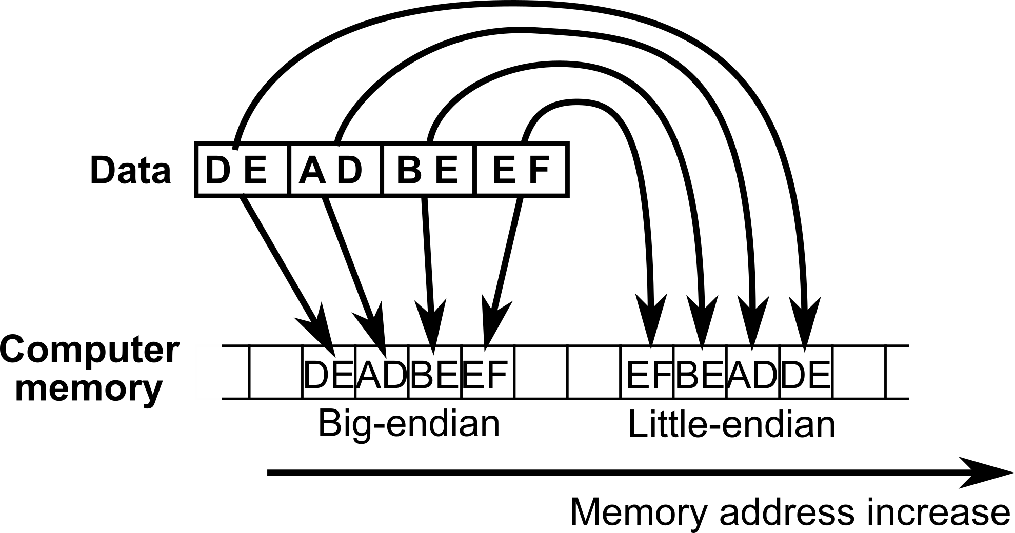
When big-endian is used then with increasing addresses bytes are stored starting from the least significant one (representing smaller values). In little endian it is otherwise so when memory is read byte by byte then data looks like bytes have reversed order. Little endian system is used in x86_64 architecture. These two endiannesses are shown on figure 1.1.
It is also possible to have different unit than single byte. In such case big-endian storage will have no difference to one shown in figure 1.1. However, if unit is for example word (two bytes) and 0xd1cec0de is to be stored then in memory it will be present as: 0xc0de, 0xd1ce. If the unit were one byte it would be stored as: 0xde, 0xc0, 0xce, 0xd1.