
Tadeusz Daszczyński
SHORT CIRCUIT CALCULATIONS – EXERCISE
The main purpose of the exercise is to familiarize students with the model example of short circuit calculations. It is proposed to perform the exercise on the basis of the actual power system. Short-circuit calculations are the basis for the selection of electrical apparatus and devices.
Basic information
Short-circuit is defined as a disturbance consisting in the connection of power network points with different potentials, resulting from the loss of insulating properties of its elements. It is accidental or intentional conductive path between two or more conductive parts forcing the electric potential differences between these conductive parts to be equal or close to zero.
Electrical installations nearly always require protection against short-circuits. The short-circuit current have to be calculated at each level in the installation for determining the characteristic parameters of the equipment required to withstand or break the fault current.
Calculation of normal operation conditions and short circuit calculations are made on the basis of electrical standards:
- IEC 60050 International Electrotechnical Vocabulary (IEV)
- IEC 60909-0:2016 Short-circuit currents in three-phase a.c. systems – Part 0: Calculation of currents
- IEC 60865-1:2011 Short-circuit currents – Calculation of effects – Part 1: Definitions and calculation methods
- IEEE Std 551-2006 IEEE Recommended Practice for Calculating Short-Circuit Currents in Industrial and Commercial Power Systems
The rules for calculating the characteristic parameters of normal operation
The basic parameters for normal operation for the calculation of the selection of electrical apparatus and devices are shown in Table 1.
Table 1. The basic parameters for normal operation for the calculation of the selection of electrical apparatus and devices
|
Characteristic parameter |
Equation |
|
|
Nominal (rated) voltage |
Un≥Un_grid |
Un – rated voltage of a device
Un_grid – rated voltage of a grid, where the device is placed
|
|
Nominal (rated) current |
In>Iload |
In – rated current
Iload – load current based on the power of supplied device
|
The main procedure for calculating short circuit parameters for LV installation is shown on Fig. 1.
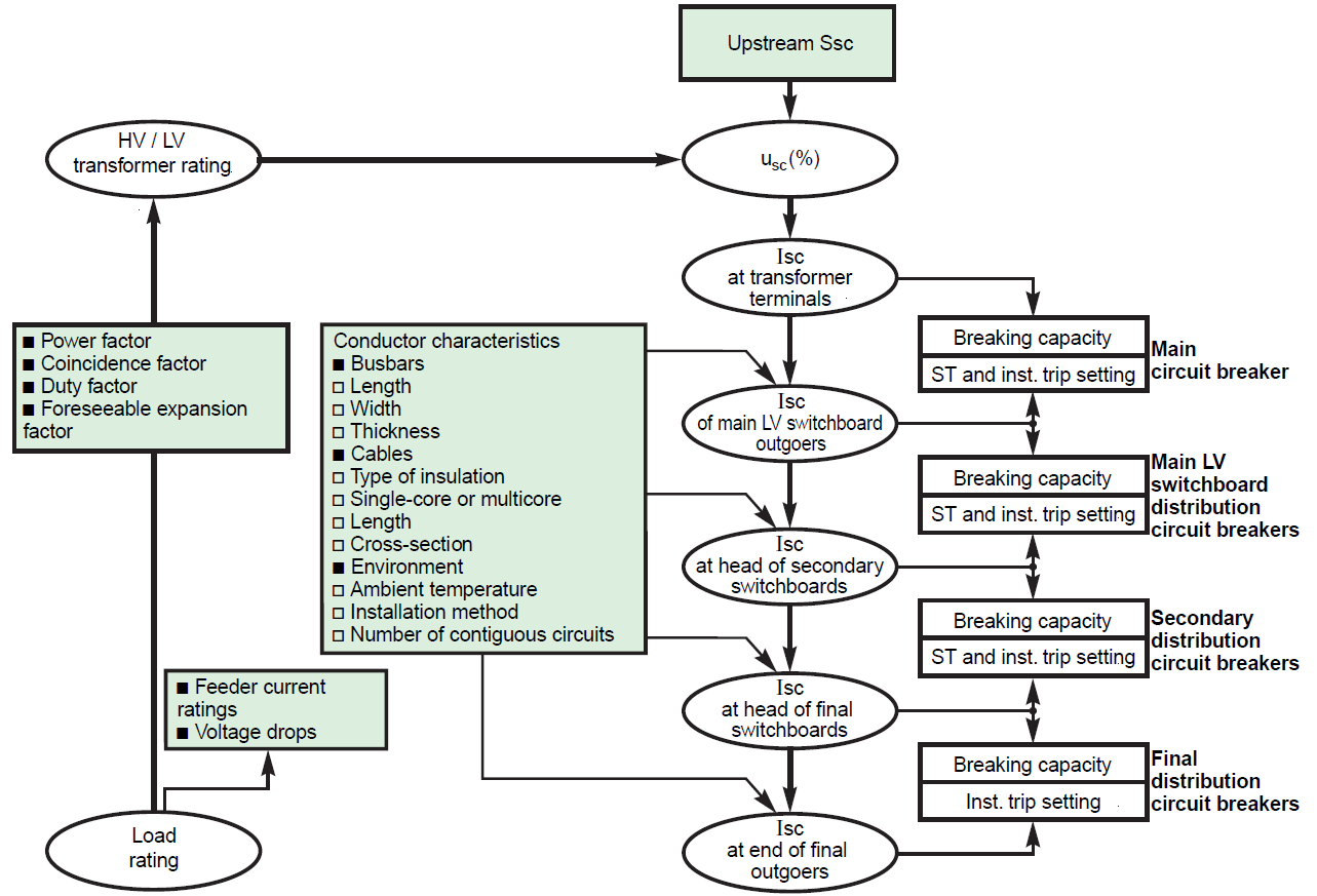
Fig. 1. Short-circuit (Isc) calculation procedure for low-voltage electrical installation (ST – short time; Inst. – instantaneous)[5]
The main characteristics of short-circuits are:
- Duration (self-extinguishing, transient and steady-state)
- Origin: mechanical (break in a conductor, accidental electrical contact between two conductors via a foreign conducting body such as a tool or an animal), internal (switching) or atmospheric overvoltages, insulation breakdown due to heat, humidity or a corrosive environment
- Location
There can be different types of a short-circuit: phase-to-eartch (80% of faults), phase-to-phase (15% of faults), three-phase (5% of faults).
Electrical devices should withstand both thermal and electrodynamic short-circuit currents. In addition, apparatusses used to connect short-circuit currents should have sufficient connectivity. The proper selection of electrical equipment is based on the appropriate selection of short-circuit parameters of the power system in the place where the device is installed. The calculation of short-circuit parameters is performed for the most difficult possible short-circuit cases, i.e. for a three-phase fault directly on the circuit breaker’s terminals. The basic short-circuit parameters of electrical apparatus include:
- Peak withstand current ipwc
where: isurge – surge current
- Short time withstand current Ik
 (2)
(2)
where: Itz – equivalent short- circuit tz-seconds current, tz – time of short-circuit
The above inequality applies for cases where tz≥n. If tz<n, then the apparatus or a device should be selected like for tz=n or its selection should be made according to the manufacturer. The duration of the short-circuit is determined by the circuit breaker nearest to the fault location.
CALCULATIONS OF SHORT-CIRCUIT CURRENTS
a) Initial short-circuit current Ipeak
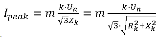 (3)
(3)
where: Un – nominal (rated) voltage of a grid, k – factor depending on the load of a system; for typical cases it is assumed as k = 1,1, m – factor depending on the type of fault; for a three-phase fault m = 1
b) Surge current Isurge
![]() (4)
(4)
where: ku – coefficient determined from Fig. 2, Ipeak – initial short-circuit current, m – factor depending on the type of fault; for a three-phase fault m = 1
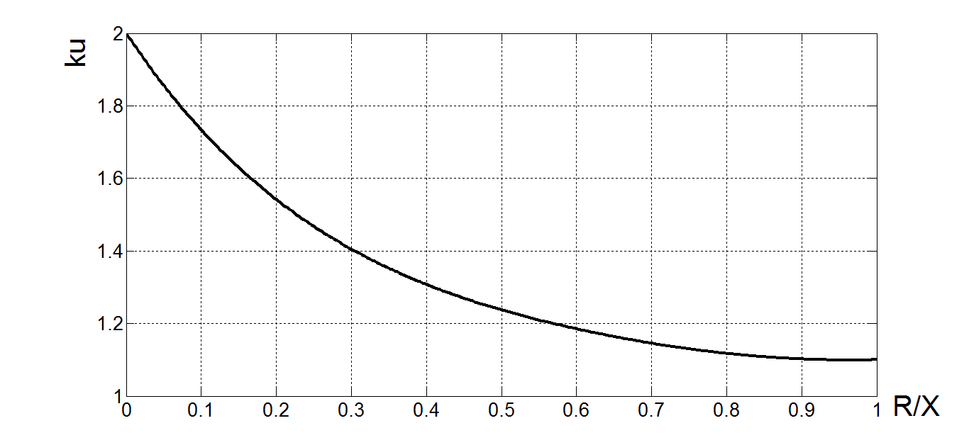
Fig 2. Dependence of an coefficient ku from the quotient R and X
c) Rated short-time withstand current Ith1s
![]() (5)
(5)
where: kc – coefficient taking into account the disappearance of the periodic current component during short circuit determined from Fig. 3, Ipeak – initial short-circuit current, m – factor depending on the type of fault; for a three-phase fault m = 1
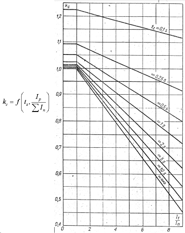
Fig. 3. Dependence of the coefficient kc from quotient I1 and In and the time of short-circuit tz [PN-E-05002:1974]
Coefficient kc is determined from Fig. 3 and depends on the duration of the fault and the ratio of the component of the initial short-circuit current and the sum of currents from all sources that can supply the short circuit. In the case of fault duration with a value other than those specified in Fig. 3, linear interpolation should be used.
Calculations for selection of current transformers
a) Current of primary side of current transformer
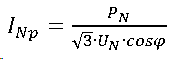 (6)
(6)b) Load power
![]() (7)
(7)
gdzie: Scables – power of losses from cables, Smeasurement – power of losses from measurement device, Scontacts – power of losses from contacts
It can be assumed that:
- Power losses on measurement device are 0,01 VA
- Power losses on contacts are 1,25 VA
- Power losses on cables need to be calculated from (8)
 (8)
(8)
The correct choice of parameters consists in checking inequalities (9) and (10).
Selection of voltage measuring transformers in MV networks
a) Voltage of primary side
![]() (11)
(11)
b) Rated isolation level
Due to the nominal primary voltage of the transformer, eg in MV networks, the rated isolation level should be selected as 17,5/38/95, where:
- 17,5 kV – highest possible voltage (RMS)
- 38 kV – rated short-time test voltage on network frequency (RMS)
- 95 kV – rated test lighting voltage (max value))
c) Rated secondary voltage of the measuring transformer depending on the connection system
![]() (12)
(12)
d) Load power
![]() (13)
(13)
gdzie: Scables – power of losses from cables, Smeasurement – power of losses from measurement device, Scontacts – power of losses from contacts
It can be assumed that:
- Power losses on measurement device are 0,01 VA
- Power losses on contacts are 1,25 VA
- Power losses on cables need to be calculated from (8)
The calculation task of choosing electrical devices
On the basis of Fig. 4, appropriate electrical equipment should be selected. The system is powered from MV network with GPZ with 3x XRUHAKXs 1×240 mm2 cables. The MV switchgear is constructed from two sections; from each section, 4 dry transformers 15 / 0.4 kV are supplied through MV circuit breakers and 3x XRUHAKXs 1 x 120 mm2 cable lines. From transformers are powered low voltage switchgears via LV switches.
For the short-circuit loop impedance calculation, use the following relationships:
- For cables
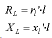 (14)
(14)
where: – unit cable resistance, – reaktancja jednostkowa linii kablowej
- for two-windings (MV/LV) transformers
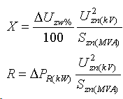 (15)
(15)
where: ΔUzw% – impedance voltage at rated current, ΔPR(kW)– rated load power losses
ATTENTION!!
When setting an impedance substitute circuit, it is important to remember that the impedance of individual elements must relate to one voltage level!
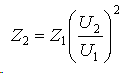 (16)
(16)
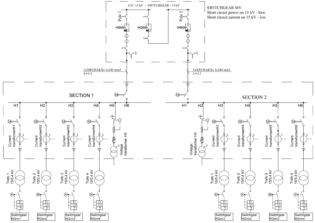
Fig. 4. Diagram of the power supply system for the task of choosing electrical devices
The data for the task is set out in Tables 2-5. The duration of the short circuit in the low voltage network should be taken at 0.4 s.
Table 2. Basic data for the calculation task
|
Team No |
Power of a system [MVA] |
Indicated transformer |
Short-circuit time in MV grid [s] |
Short circuit power of a system– multiplier |
|
1 |
50 |
Section 1 – trafo 1 |
1,6 |
2 |
|
2 |
60 |
Section 1 – trafo 2 |
1,4 |
3 |
|
3 |
80 |
Section 1 – trafo 3 |
1,2 |
4 |
|
4 |
90 |
Section 1 – trafo 4 |
1,0 |
1,5 |
|
5 |
120 |
Section 2 – trafo 1 |
0,8 |
2,5 |
|
6 |
85 |
Section 2 – trafo 2 |
0,9 |
7 |
|
7 |
75 |
Section 2 – trafo 3 |
0,7 |
5 |
|
8 |
55 |
Section 2 – trafo 4 |
0,5 |
10 |
|
9 |
65 |
Section 1 – trafo 3 |
1,0 |
3,5 |
|
10 |
45 |
Section 1 – trafo 4 |
1,5 |
5 |
|
11 |
90 |
Section 2 – trafo 1 |
1,3 |
6 |
|
12 |
110 |
Section 2 – trafo 2 |
1,1 |
5,5 |
Table 3. Rated parameters of transformers 15/0,4 kV
|
Indicated transformer |
Nominal (rated) power [kVA] |
Impedance voltage at rated current [%] |
Rated load power losses [W] |
The length of the cable line powering the device [m] |
|
Section 1 – trafo 1 |
2000 |
4 |
16000 |
1000 |
|
Section 1 – trafo 2 |
1600 |
6 |
13000 |
800 |
|
Section 1 – trafo 3 |
1000 |
8 |
9000 |
850 |
|
Section 1 – trafo 4 |
3150 |
10 |
22000 |
700 |
|
Section 2 – trafo 1 |
3150 |
4 |
22000 |
1100 |
|
Section 2 – trafo 2 |
1000 |
6 |
9000 |
560 |
|
Section 2 – trafo 3 |
1600 |
8 |
13000 |
485 |
|
Section 2 – trafo 4 |
2000 |
10 |
16000 |
1050 |
Table 4. Additional parameters to complete the task
|
No in team |
ψ |
Length of a cable L1 [m] |
|
1 |
3,5 |
200 |
|
2 |
3,3 |
250 |
|
3 |
3,1 |
150 |
|
4 |
2,8 |
320 |
Table 5. The rated parameters of cable lines
|
Cable |
Unit resistance [Ω/km] |
Unit reactance [Ω/km] |
|
XRUHAKXs 1×240 |
0,125 |
0,58 |
|
XRUHAKXs 1×120 |
0,253 |
0,182 |
You can use the MATLAB software and the script below to plot the short-circuit current. The output data is: the effective value of the short-circuit current in kA, the phase of current switching in rad, the short-circuit time in s.
MATLAB programme
clear all;
close all;
clc;
format compact;
disp(‘The effective value of the short-circuit current [kA]’);
I = input(‘I = ‘);
disp(‘Phase of current switchingw [rad]’);
psi = input(‘psi = ‘);
disp(‘Short-circuit timew [s]’);
tz = input(‘tz = ‘);
Im = I*sqrt(2)*1e3;
fi = pi()/2;
T = 0.07;
w=314;
for n = 1: tz*10000
t(n) = (n-1)*1e-4;
iok(n) = Im*(sin(w*t(n)+psi-fi));
inok(n)=Im*(exp(((-t(n))/T)))*sin(psi-fi);
end
An exemplary course of short-circuit current is shown in Fig. 5.
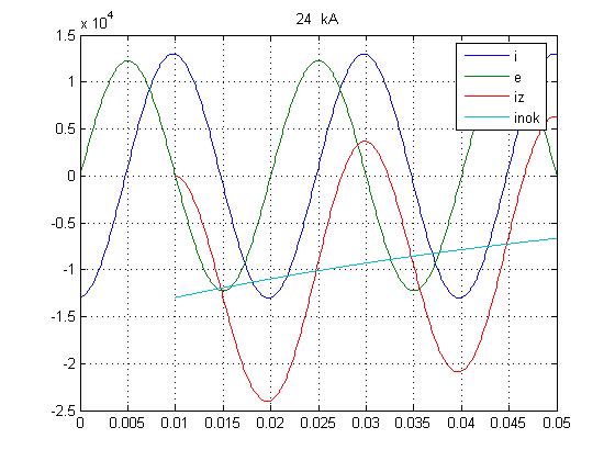
Fig 5. An exemplary course of short-circuit current
The Simpson equation should be used to calculate the substitute short-circuit current value (17).
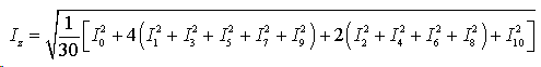 (17)
(17)
Report must contain at least:
- Scheme of a system
- Equivalent scheme of a system (short-circuit scheme)
- normal operation calculations and short circuit calculations
- selection of indicated electrical devices (catalog sheets)
- short circuit current waveform on the low voltage side
- calculation of short circuit current
- IEC 60050 International Electrotechnical Vocabulary (IEV)
- IEC 60909-0:2016 Short-circuit currents in three-phase a.c. systems – Part 0: Calculation of currents
- IEC 60865-1:2011 Short-circuit currents – Calculation of effects – Part 1: Definitions and calculation methods
- IEEE Std 551-2006 IEEE Recommended Practice for Calculating Short-Circuit Currents in Industrial and Commercial Power Systems
- B. de Metz-Noblat, F. Dumas, Ch. Poulain, „Cahier technique no. 158 Calculation of short-circuit currents”, Schneider Electric