
Tadeusz Daszczyński; Waldemar Chmielak; and Zbigniew Pochanke
DIAGNOSTICS OF HIGH VOLTAGE CIRCUIT BREAKERS
Introduction
The aim of this exercise is to get acquainted with the structure and basic functions of Merlin Gerin MV switchgears: to the ring network (RM6) and to the radial network (SM6). During the exercise, the construction and operation of the drive mechanism of the low-oil circuit breaker SCI4 will be examined, the method of reinforcement of the SCI4 circuit breaker and the recording of the SCI4 circuit breaker movement characteristics.
The circuit breaker is a device that ensures the control and protection on a network. It is capable of making, withstanding and interrupting operating currents as well as short-circuit currents. The main circuit must be able to withstand without damage:
- The thermal stress caused by the short-circuit current during 1 or 3 s
- The electrodynamic stress caused by the peak of short-circuit current:
– 2.5 x Isc for 50 Hz (standard time constant of 45 ms)
– 2.6 x Isc for 60 Hz (standard time constant of 45 ms)
– 2.7 x Isc (for longer time constant)
- The constant load current.
Since a circuit breaker is mostly in the “closed” position, the load current must pass through it without the temperature running away throughout the equipment’s life.
Compulsory rated characteristics of MV circuit breakers are (IEC 62271-100):
a) rated voltage
The rated voltage is the maximum rms value of the voltage that the equipment can withstand in normal service. It is always greater than the operating voltage.
b) rated insulation level
The insulation level is characterised by two values:
- the lightning impulse wave (1.2/50 μs) withstand voltage
- the power frequency withstand voltage for 1 minute.
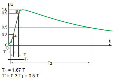
Fig. 1. Full lightning impulse
c) rated frequency
d) rated normal current
With the circuit breaker always closed, the load current must pass through it in compliance with a maximum temperature value as a function of the materials and the type of connections. IEC sets the maximum permissible temperature rise of various materials used for an ambient air temperature not exceeding 40°C.
e) rated short-time withstand current
This is the standardised rms value of the maximum permissible short-circuit current on a network for the rated duration of short-circuit.
(1)
where: Ssc – short-circuit power in [MVA], U – operating voltage in [kV], Isc – short-circuit current in [kA]
f) rated peak withstand current
The making current is the maximum value that a circuit breaker is capable of making and maintaining on an installation in short-circuit. It must be greater than or equal to the rated short-time withstand peak current. Isc is the maximum value of the rated short-circuit current for the circuit breakers’ rated voltage.
g) rated duration of short-circuit
h) rated supply voltage of closing and opening devices and of auxiliary circuits
i) rated supply frequency of closing and opening devices and of auxiliary circuits
j) rated pressures of compressed gas supply and/or of hydraulic supply for operation, interruption and insulation, as applicable
k) rated short-circuit breaking current
The rated short-circuit breaking current is the highest value of current that the circuit breaker must be capable of breaking at its rated voltage. It is characterised by two values:
- the rms value of its periodic component, given by the term: “rated short-circuit breaking current”
- the percentage of the aperiodic component corresponding to the circuit breaker’s opening time, to which we add a half-period of the rated frequency. The half-period corresponds to the minimum activation time of an overcurrent protection device, this being 10 ms at 50 Hz.
l) transient recovery voltage related to the rated short-circuit breaking current
This is the voltage that appears across the terminals of a circuit breaker pole after the current has been interrupted. The recovery voltage wave form varies according to the real circuit configuration. A circuit breaker must be able to break a given current for all transient recovery voltages whose value remains below the rated TRV.
m) rated short-circuit making current
n) rated operating sequence
o) rated time quantities.
Isolation test
The isolation of circuit breakers consists of various insulating materials – gas, liquid, dielectric solid materials. The breaker insulation faults occur as a result of a breakdown between phases, to the ground or between open contacts. The breakthrough of the breaker insulation is usually a dramatic event leading to serious damage or destruction of the device.
The condition of the insulation system inside the circuit breaker chamber depends on the level, density and pressure of the medium, which values must be above the assumed minimum value. For most switches, measurements of these values are possible continuously using appropriate transducers or indicators. In pneumatic and gas switches with SF6, pressure is mainly measured. On low and full oil circuit breakers – oil level. Only the measurement of the vacuum condition of vacuum circuit breakers is by far the most difficult and is not practically possible in a continuous manner during normal operation of the switch.
One of the basic techniques for all types of insulation quality measurement connectors is the measurement of insulation resistance. This parameter is easily measurable using commercially available meters. However, it requires disconnecting the apparatus from the system in which it normally works. Cyclic measurement of insulation resistance can indicate degradation of insulation over time. However, the lack of changes in this parameter does not guarantee that the insulation is in good condition. Therefore, it is not the best method of diagnostics of insulation systems and can only be a supplement to other methods.
Serious damage to solid, oil and gas insulation is usually preceded by partial discharges (PD). Therefore, partial discharge tests can be a very good indicator of the deterioration of the insulation condition. Unfortunately, such measurements are not possible on circuit breakers operating in the network due to excessive interference from the operating power system. The exceptions are gas-insulated switchboards, which have a grounded housing allowing the installation of sensitive measuring systems.
Testing of current circuits
Conduction of nominal currents causes heating of current paths and contacts. The process of contact degradation usually proceeds quite slowly at the beginning, after which it can rapidly accelerate after several years, leading to contact burns and gaps in the circuit. Thus, most problems can be detected by odd diagnostic tests. The introduction of continuous monitoring of the condition of the main current circuits may allow predicting lesser damage. The simplest signal possible for continuous recording is the value of the load current. This allows to determine how heavily the device is exposed. Modern measuring and protection systems allow for detailed recording of all operating states with high resolution using existing measuring devices – current transformers.
The basic technique of testing the current paths is to measure the resistance of contacts. For this purpose, a direct current source is used, which, when connected to the tested current path, causes voltage drops in particular elements of the current path (Fig. 2). Measurement of voltage drops on these elements allows to determine their resistance with a technical method.
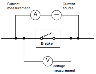
Fig. 2. Scheme of the circuit to measure the resistance of contacts
The contact resistance of high voltage switches is in the order of 10 – 100 μΩ. In order to obtain the proper accuracy of the measurement, it is recommended to force the current flow at 50 – 100 A. For circuit breakers rated at several thousand amperes, it is recommended that the current of the measurement system be at least several hundred amperes. This method of measurement, although very accurate and effective in determining the degradation of contacts, has a fundamental disadvantage – the need to disconnect the circuit breaker from the mains.
The effects of contact degradation can also be measured by indirect methods by measuring their heating. For this purpose, transducers permanently installed on the switch – thermocouples, optical sensors, pyrometers can be used, or make measurements with a thermal imaging camera during, for example, visual inspection. Thermal imaging studies seem to be one of the most popular and valuable methods of assessing the heating state of individual elements of current paths. Such studies are not particularly demanding and complex, and they can quickly and clearly indicate anomalies in the system.
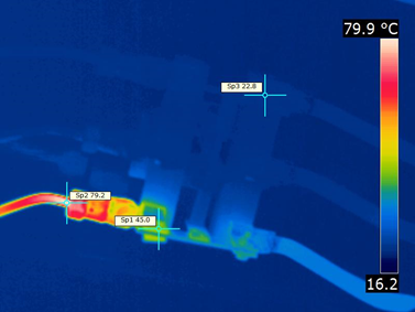
Fig. 3. Picture from thermal camera
Connection measurements
Switching functions of circuit breakers, although they constitute a negligible fraction of the lifetime of switches, seem to be particularly important from the point of view of the power system as well as the reliability and durability of the switch itself. Depending on the type of switch, its location in the power system, the topology of the system and the type of power being turned off, thermal, mechanical and dielectric exposure can be very different and within a wide range. Switching on or off in such conditions can lead to sudden damage to the circuit breaker. Fortunately, most possible types of damage do not occur without previous symptoms.
The basic information read from the connector is the location of its contacts. It is extremely important for both control systems and the power system itself. In addition, counting the number of changes in the position of contacts, especially when connecting significant currents, can generate important information about the wear life of the switch. In switches in which the movable contacts are mechanically connected to the drive mechanism, especially on the ground potential, the contact position indication is not particularly difficult. Electronic, electromechanical or optical transducers are used for this purpose. Most often it is an electromechanical auxiliary switch connected directly to the drive mechanism. In some switches, for example with pneumatic drive, where there is no mechanical connection between the movable contact and the earthed element, the measurement of the position of the contacts is more difficult and subject to erroneous indications. Optical transducers are the best solution, the more they are resistant to electrical interference and galvanically isolated they can measure the displacement of the element at the highest potential. Such solutions, however, are not widely used, mainly for economic reasons.
A characteristic feature of the movement of the contacts of movable electrical switches is the transient character. During the switching operation, the moving system is accelerated, sustained and braked. The use of measuring transducers increases the possibilities of obtaining data from the tested object. Some transducers allow not only to save the motion characteristics in the form of a time-to-time relationship but also by using simple mathematical operations to determine the acceleration or speed. Electrical or resistive transducers are used to measure the motion parameters of electrical apparatus. There are also other transducers to measure the path, even optical / laser pickups, but because of the price and complexity of measurement difficulties are not yet as popular.
Resistance transistors in the form of precision potentiometers are made of wound wire resistors or conductive plastic, on which a moving contact moves. The measuring potentiometer is attached to the breaker body and the movable contact to the moving contact drive element. The measuring system (Fig. 4), usually in the form of a bridge, is supplied from an auxiliary DC voltage source. The measured voltage has a value proportional to the current position of the mechanism.
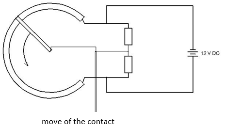 |
Fig. 4. Measurement setup for measuring the move of the contact
An exemplary waveform of movement of the contact of the vacuum circuit breaker is shown in Fig. 5. A detailed comparative analysis of the measured waveforms with those previously registered allows for inference about the evolving damage leading to permanent damage. For proper analysis of the waveforms, it is necessary not only the previously registered motion characteristics, but also detailed knowledge of the permissible deviations for individual switchgear designs and the causes that cause them. In addition, be aware that not always recorded deviations in the mileage must indicate a deterioration of the state of the circuit breaker. The slower movement of contacts when opening does not necessarily indicate the wear of the mechanism, but it may be due to the fact that a fully charged drive of some circuit breakers has more dynamics than partially discharged after the switching cycle. Exemplary deformations of contact movement curves and related damage mechanisms are shown in Fig. 6.
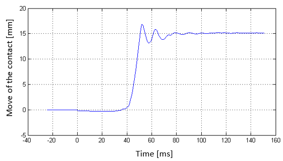 |
Fig. 5. An exemplary waveform of movement of the contact of the vacuum circuit breaker
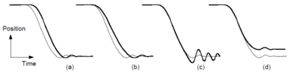
Fig. 6. Comparison of waveforms of movement of the contact during opening
The dotted line in Fig. 6 indicates the characteristics of the new circuit breaker, the continuous line – distorted characteristics due to: a) trigger delay eg. due to deceleration of the trigger after overheating or contamination of moving parts, b) deceleration of motion eg. due to reduction of drive system energy , c) weaker attenuation related to the wear of dampers, d) reduction of the contact gap (insulating), eg. due to slack in the drive mechanism.
The speed measurement is carried out using inductive transducers. They use the effect of motion or position of the object on the magnetic properties of the transmitter’s circuit. We divide these methods into generative and parametric ones. It is associated with the requirements for the necessity or non-use of energy that mediates in the measurement procedure. In generation methods, an electrical signal is generated in the transducer due to the conductor movement in the magnetic field. The simplest speed transducer is a coil moving in a magnetic field. The voltage induced on this coil is proportional to the derivative of the displacement giving the output a signal proportional to the speed.
Based on the displacement measurement, we can get information about individual stages in the process of opening or closing the circuit breaker. Fig. 7 and 8 show the displacement of a movable contact registered as a voltage change over time in the cycle of opening the vacuum circuit breaker (Fig. 7) And closing of the low oil circuit breaker (Fig. 8). On the basis of recorded runs of the closing process of the low-oil circuit breaker shown in Fig. 8, it is possible to divide a given cycle into individual stages. The figure also shows other basic waveforms recorded during standard diagnostic tests of circuit breakers. These are changes in the dynamic resistance of the contacts and the current in the trigger coils. Such a combination allows to enlarge the information resource about particular stages in the switching process of the connector.
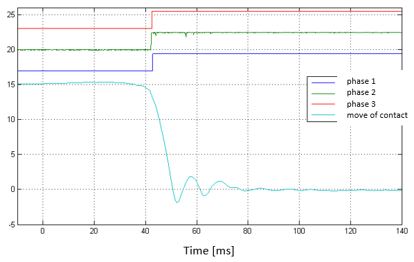 |
| Fig. 7. Move characteristics of vacuum circuit breaker |
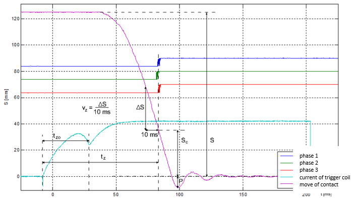 |
Fig. 8. Move characteristics of oil circuit breaker
The tzo and tz times determine the trigger’s own time at switch on and the switch’s own time needed to make contacts. Most manufacturers give these times along with tolerances in the breaker specifications. Measuring these times is the simplest method of evaluating the state of the circuit breaker and does not require waveform recording. It is similar with the measurement of time and current of the reinforcement of the propulsion mechanism.
Electromechanical diagnostics of the circuit breaker operation requires measurement of the contact gain / loss moment. Such a measurement allows to determine many parameters of contact movement, such as the time of unequality of contact gain / loss Δtz, time tod of bounce, and including other waveforms: the circuit breaker’s own time, the open contact gap, the depth of the movable contact depth. This is accomplished by measuring the so-called dynamic resistance of contacts. The supply of DC voltage from the accumulator battery through a resistor on each pole of the circuit breaker allows for instantaneous (stepless, zero-failure) change of the voltage on the contacts depending on the state of contact. When the contact is lost, the voltage on the contacts changes abruptly to the supply voltage of the measuring system. When the contacts come down, the voltage changes to zero. If there are bounces, a sudden change in voltage follows with the change of the contact state. The measurement execution scheme of this parameter is presented in Figure 9. Examples of changes in the dynamic resistance of contacts are shown in Figure 10.
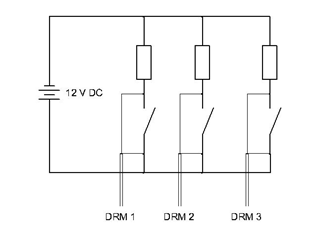
Fig. 9. The measurement execution scheme
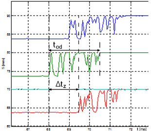
Fig. 10. Examples of changes in the dynamic resistance of contacts
TESTING OF AUXILIARY CIRCUITS
Activation of drive mechanisms causing the switching of power apparatus must be initiated by triggering the triggering element. Typically, regardless of the type of drive (mechanical, pneumatic, hydraulic), the release is a solenoid supplied from 110-220 V DC. Also, switches with a motor mechanism (disconnectors, earthing switches) are triggered by electromagnets that trigger the current on the drive motor. Despite the simplicity of such a triggering system, it is the most unreliable element in the entire structure of the reliability link, which is confirmed by international statistics. The most common effect of a malfunctioning trigger is delays in the operation of the breaker. This is not a particularly severe defect, but can often lead to less frequent major failures associated with not joining or, worse, failure to turn off the circuit breaker, which can lead to serious power system failures. Diagnosis of this subassembly seems to be the most reasonable and valuable and therefore it is most often practiced. The more so that it can be based only on the simple and cheap registration of the electromagnet current, which in a way is a measuring transducer of its own motion.
An example of the current of the trigger coil of medium voltage canister circuit breaker is shown in Figure 11. From the recorded waveform, in addition to determining the own times, as shown in the figure, showing the dynamics of the trigger action, two characteristic values of the current Im and Ie can be determined. Based on the experience and relevant knowledge of such parameterized waveforms, one can infer about the condition of the triggering system.
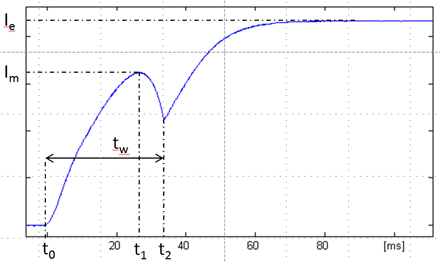
Fig. 11. Waveform of current of the trigger coil of MV circuit breaker
THE COURSE OF THE EXERCISE
- Switchgear display (purpose, construction and functions of components, interlocks).
- Write down the nameplate and rating of the SCI4 circuit breaker from the rating plate.
- Draw a schematic of the measurement system: 1) current of the release coils, 2) contact times, 3) contact path (potentiometer bridge).
- Familiarize yourself with the construction of the breaker poles (pole diagram, visual inspection of contacts), recognize the direction of rotation of the main drive shaft on the direction of contact movement.
- Recognize the mechanism of the SCI4 circuit breaker, learn how to reinforce and trigger the drive.
- Measure the motion characteristics of the SCI4 circuit breaker, with two different levels of supply of the release coils: 1) for opening: U = 0.7 Un, U = 1.15 Un, 2) for closing: U = 0.85 Un, U = 1.15 Un.