
Tadeusz Daszczyński; Zbigniew Pochanke; and Waldemar Chmielak
SWITCHING OFF THE ALTERNATING CURRENT WITH CONTACTORS: A LABORATORY EXCERCISE
Purpose of the excercise
The purpose of exercise is to show the processes of switching on and off alternating current, phenomena taking place in the area between contacts and the construction and operation of the contactors. The exercises presents the impact of interruption of neutral cable on the switching process. Phenomena of switching of AC was both analyzed theoretical and practical with measurements. The laboratory set-up is presented with short description and results from operating.
Keywords alternating current, contactor, switching off, laboratory set-up
Introduction
Teaching of electrical apparatuses and organization courses often brings problems, especially to help students to understand the structure of the electrical device in relation to complex techniques of switching on/off currents. The problem concerns of both AC and DC. Without proper knowledge students cannot solve real problems, so the main goal for teachers is to explain theory and show its practical implementation. For course of electrical apparatuses one of the most important problem is to switch off alternating current.
The main aim of experiment is to show students switching processes in AC, processes occurring in the interstitial space and the construction and operation of AC contactors. AC contactors are the largest low-voltage group of these devices. The most common and widely used group is the electromagnetic contactors. Depending on the type, they are divided into single or multi-pole, single or multi-hinged, with horizontal or vertical mounting. The low voltage contactors with 4 poles was shown on Fig. 1.
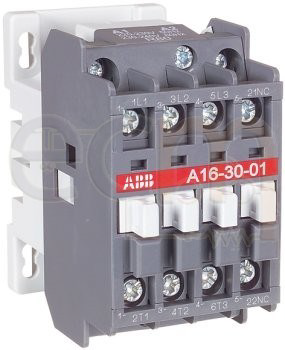
Fig. 1. The low voltage contactors with 4 poles [ABB]
The basic construction elements of contactors are:
- base or body,
- drive mechanism (electromagnet),
- main circuits (switching circuit and breaking chamber).
On Fig. 2 the contactor with double pole with horizontal basis is shown. Solenoid jumper with crossbar, lever system and cams, main and auxiliary contacts are classified as moving parts. Fixed elements are the base or the body, the magnetic core with the winding, control circuit wires, moving parts, fixed and auxiliary contacts, terminals and connecting elements, blowing magnets and windings and drainage chambers.
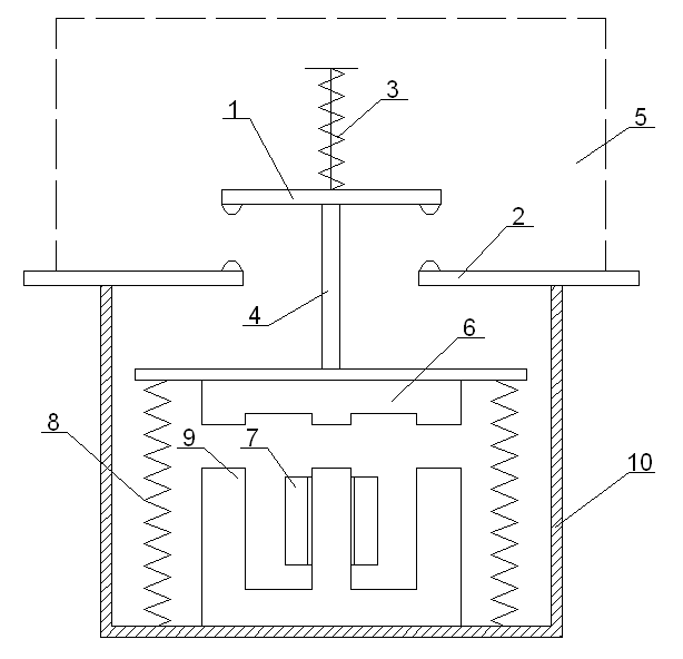
Fig. 2. The contactor with double pole with horizontal basis: 1, 2 – moving and fixed contacts; 3 – spring contact (pressure); 4 – crossbar; 5 – breaking chamber; 6 – electromagnetic valve; 7 – drive winding; 8 – return spring; 9 – elektromagnet core; 10 – body.
Switching process in AC
Arcing for AC electrical apparatus can occur in two ways:
- when the SEM value of the network is much lower than the puncture voltage for the cold electrodes. The arc is then caused by the very high temperature of the last point of contact and by the increased voltage caused by the inductance of the mains supply.
- as a result of the re-ignition of the return voltage after the arc has extinguished.
In switching technique there are usually used gases: SF6, N2, CF2Cl2 and air (approximately 80% N2 and 20% O2). In normal atmospheric conditions, in low electric field, the air is nearly ideal dielectric. A small conductivity (10-16 – 10-17 A/cm2) is caused by cosmic influence and radioactive radiation visible on the surface of the Earth and in the atmosphere. When applied to an electric field, the energy of the collision of charged particles with neutral
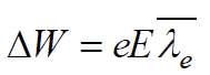
particles may increase and cause the crash collision. In elastic collisions, the loss of electron energy is usually small, in contrast to inflexible, where a large proportion of kinetic energy is converted to potential energy, resulting in ionization of the impacted particle. The effectiveness of collision ionization depends on the energy that the electron reaches along the mean free path toward the field. To cause the ionization collision the energy (1) of electron should be equal or higher than the energy of particle (eVi).
 (1)
(1)
where: ΔW – average energy achieved by the electron along the mean free path ![]() in the direction of a field with intensity E.
in the direction of a field with intensity E.
Electrons with lower energy ΔW can excite free particles, which can be ionized at the next collision with low energy electrons. Not every electron of energy ΔW≥ eVi can cause ionization during collision. The whole process must be recognized as random event. For energy below the ionization level the collision of electrons with free particles can lead to the excitation of an atom which, when collided with another slow electron, can ionize. This process is characterized by high numbers of electrons. Fast electrons can pass the atom without breaking another electron.
In the absence of an electric field, the steady state of the gas can be maintained if the number of electrons and positive ions is equal. This condition can be disturbed by applying a significant electric field. Townsend was the first to measure the variability of the gas current measured between two parallel electrodes as a function of applied voltage. The Townsend’s discovery was shown on Fig. 3. The current in the beginning rises proportionally to the applied voltage (up to level U1). Up to level U2 reaches the steady value i0, which corresponds to current saturation – the ionization process is stabilized. For voltage higher than U2 the particles reaches the critical values of speed and kinetic energy, so they can collide inflexible with neutral molecules of gas.
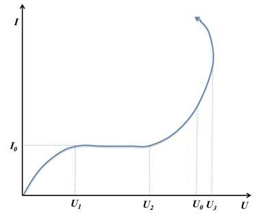
Fig. 3. The dependence of the current on the voltage of the Townsend mechanism
Ionizing collisions can initiate avalanche discharge, and subsequent collisions cause an increase in the number of charges and currents. When there is no external impact, the discharge process disappears, so the avalanche discharge is a non-independent discharge. The next steps of a discharge can be different and it is influenced by field uniformity, electrode spacing, gas pressure. There are three basics mechanisms of discharge:
- Townsend – for low values of the product of the distance between the electrodes and the gas pressure (100-1000 hPa∙cm),
- channel (streamer) – 103-105 hPa∙cm and streamer-leader – higher than 105 hPa∙cm
- vacuum.
The electron avalanche characterizing early stage of a breakdown is common for all mechanisms without vacuum. In the moment of beginning of breakdown in the interstellar space, the values of stress and voltage reach critical values E0 i U0. Values for both are possible to determine by
Townsend’s criteria (2).
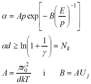 (2)
(2)
where: α – Townsend’s first ionization coefficient, d – spacing of electrodes, p – gas pressure, E – electric field, γ – Townsend’s second ionization coefficient, Nk – critical number of ionizing collisions caused by 1 electron in the path a.
For constant temperature the coefficients A, B, Nk are also constant, so the voltage U0 is dependent on the spacing of electrodes and gas pressure, what is shown in (3).
![]() (3)
(3)
The equation (3) is known as Paschen’s law (shown on Fig. 4) and was discovered in 1889. The minimum of a function can be explained qualitatively by taking into account the efficiency of ionization by electrons with different levels of energy in interstellar space. Neglecting coefficient γ for pd > (pd)min electrons more often collide with the gas molecules than in (pd)min, but energy obtained between the collisions is less than for the level (pd)min. The probability of ionization is smaller, so for increasing it the voltage should be higher. For pd < (pd)min electrons can flow through the inter-electrode space without collision.
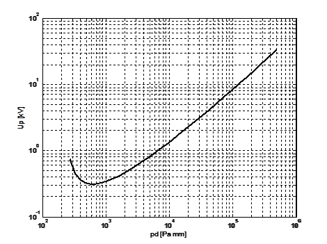
Fig. 4. Paschen’s curve
Paschen’s law can be used for value pd up to 1,3-2,6 bar∙cm. Above these values, the jump voltage tends to increase with increasing inter-electrode spacing. For low pressure incompatibility of Paschen’s law is due to a change in the mechanism of initiation of avalanche jump into an arc discharge in pairs of metal emitted from electrodes.
Switching on AC
The process of switching on AC with use of contactor is connected with mechanical process where a collision of two elastic masses occurs. Moving contact with speed related to the type of a device, hits the fixed contact, which causes vibration or even spring bounces of contacts. These vibrations can complicate the process of a collision (the number of bumps, their duration), which is particularly important, for example, in electronic control systems, where bumps can cause multiple shocks. Rebounce of contacts can cause electric arc ignition, leading to their erosion and/or grafting. For category AC3, where the switching on voltage is much higher than during switching off, the level of recoils decide about switching life of the contactor.
On the Fig. 5 the RL circuit substitution scheme was shown. The RL branch represents the electric motor. The rated contact current for the motor circuits should be equal to the starting current, so the choice of the apparatus depends on the type and power of the motor. Regardless of the start-up conditions, the starting currentflows through the contactor at the start-up phase is equal to locked-rotor current. As the speed increases, this current decreases to a value determined by the operating conditions of the motor. Depending on the start-up conditions (idle, intake, various loads) the starting current decreases slowly or faster. Particularly harsh conditions when switching on AC circuits are: reversing of engine rotation and counter current, switching on the capacitor banks.
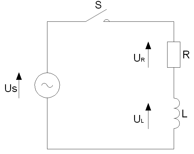
Fig. 5. RL circuit substitution scheme
The contactor should be able to switch on the value of the starting current, so the selection of the device must depend on the type and power of the motor.
Figures 6 and 7 show the current waveforms of the induction motor in idle state and with locked rotor. In the initial phase, when the motor does not reach the rated speed, the current has a higher value (starting current). After some time, it reaches its rated work values (Fig. 6). The locked-rotor current is basically equal to the starting current (Fig. 7). The drawings also show the switching off of the induction motor. It is clearly visible that the currents of individual phases are not switched off at the same time. The individual phases on the 50 Hz three-phase power supply are offset 120° from each other and, according to their shift, they should be switched off when the current passes the “zero”. Presented waveforms have been registered in the system with isolated zero point. In such a system, after interrupting the current in one phase, a one-cell system is created, in which the currents in phases that were not switched off are deformed, because they become the same current and simultaneously pass through zero.
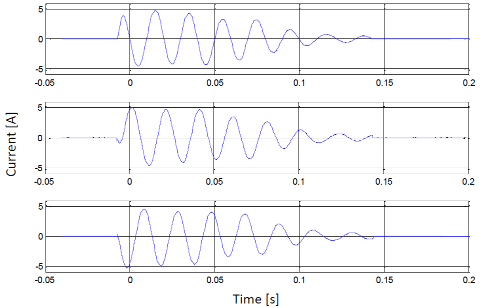
Fig. 6. Currents in each phase for inductor motor in idle state
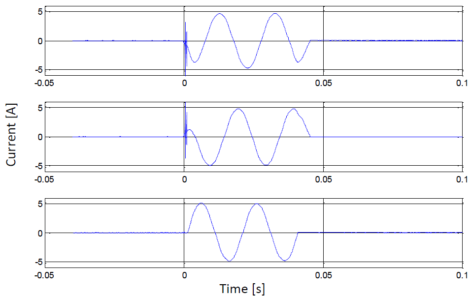
Fig. 7. Currents in each phase for inductor motor in short-circuit state
Switching off AC
The general condition of switching off the current with the initial value Iw can be defined as:
![]() (4)
(4)
where and ia – the current value of the arc current.
The condition (4) is realized in AC systems without the participation of a switch, because periodically the voltage of the source forces the flow of alternating current. This current passes through the zero value 2f times per second, and thus meets the above condition also 2f times per second. Each transition through zero is accompanied by the extinction of the arc. After breaking the arc, between the contacts of the connector, appears the transient recovery voltage (TRV), the course of which is a component of the source voltage and transient oscillations generated by the reactances of the circuit. However, this arc can ignite again if there is insufficient ignition voltage when the transient recovery voltage increases. It is clear from this, that if the apparatus creates the appropriate conditions to prevent re-ignition after the arc goes out, then the fact of a natural zero crossing can be used to effectively extinguish the arc without the need to lengthen it (as it is in switching off DC).
In general, the condition of effective AC arc extinguishing can be formulated as: before passing the arc current through natural zero, the heat from the arc channel should be intensively absorbed, after passing through the natural zero (arc extinguishing) it is necessary to ensure effective de-ionisation of the arc channel in order to obtain the proper ignition voltage.
Conductivity of the channel at the moment of passage of the arc current through zero can be a measure characterizing the efficiency of cooling the arc channel. It depends on:
– efficiency of power reception from the arc channel (the higher the reception, the smaller the conductivity),
– the value of the temporal component of the arc (the smaller the time component, the smaller the conductivity),
– the value of the switched off current (the smaller the breaking current, the smaller the conductivity),
– arc channel length (the longer the channel, the smaller the conductivity).
The effective turn off current will occur when the contact break will withstand the return voltage rising without re-ignition. The return voltage can be defined as the voltage difference: on the terminal pole of the connector from the source side and on the pole terminal on the short-circuit side. This voltage is caused by a transient state after switching off the current and is one of the parameters relevant to the selection of connectors for the right type of work.
In the circuits that electric supply the induction motors the voltage courses for each phase are shown on Fig. 8 (idle state) and Fig. 9 (short circuit state). After switch off current (about 0,14 s) the course of voltage in idle state is decreasing – it does not disappear at once. This is due to the nature of the receipt – the induction machine can work as a motor (powered by a 3-phase source) or as a generator.
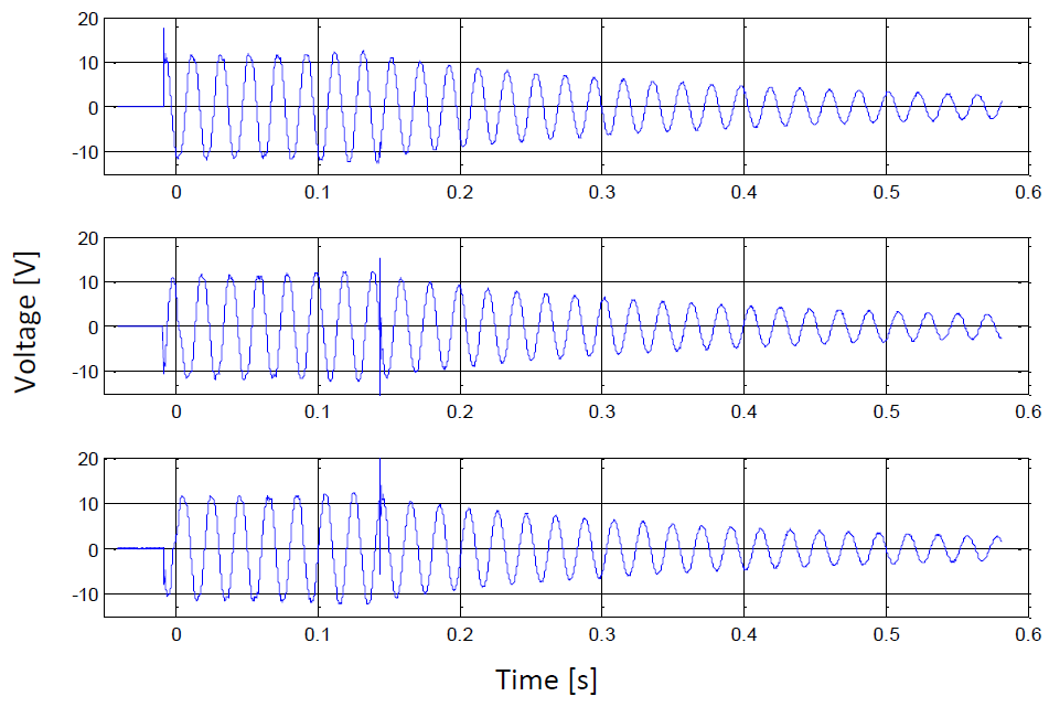
Fig. 8. Voltage on each phase for supplying induction motor on idle state
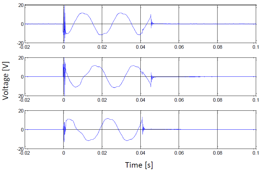
Fig. 9. Voltage on each phase for supplying induction motor on short-circuit state
When switching off three-phase circuits, the currents of individual phases are not switched off at the same time, even though the connector contacts propagate simultaneously. This is the result of the phase shift of voltages and currents in individual phases. A special case here is switching off induction circuits (e.g. motor) with an isolated neutral point (Fig. 6). As the first one switched off the first phase.
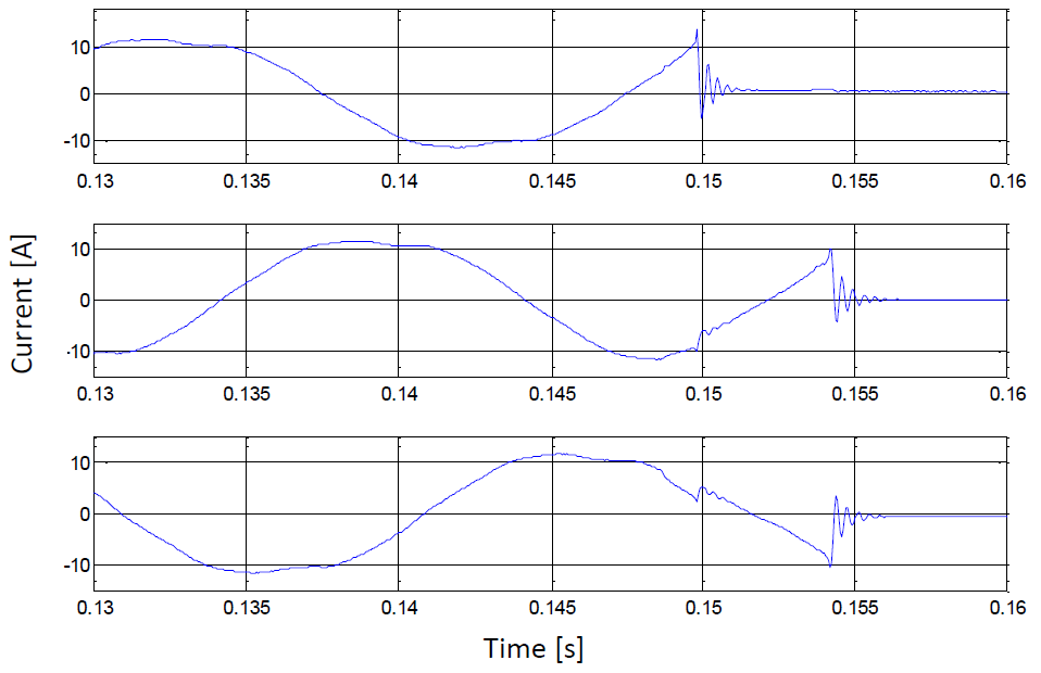
Fig. 10. Switching off three phase AC system with isolated neutral
Laboratory setup
The laboratory setup is located in Short-circuit LAB in Warsaw University of Technology, Department of Electrical Engineering. It is built from the voltage source (230/400 V AC, 50 Hz), voltmeter, ammeter, 4-pole contactor, time trigger plugged into only contactor circuit, current and voltage transformers, induction motor. On Fig. 11 the view of the mainboard of the laboratory stand for switching off the AC current is shown. All measurements are recorded using a digital oscilloscope set under the main board. The instructor is to familiarize the team performing the exercise with the operation and functionality of the recorder. On Fig. 12 the view of the rating plate of the induction motor is shown.
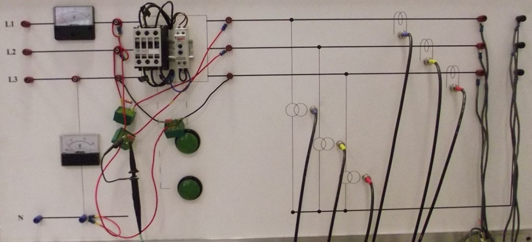
Fig. 11. View of the mainboard of the laboratory stand for switching off the AC current
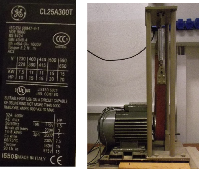
Fig. 12. View of the rating plate of the induction motor
The laboratory stand is powered from an electrical board located on the laboratory wall. The board has circuit breakers and a contactor. Each switching action during the exercise should be performed under the supervision of the teacher and after the first connection made by the teacher.
The student’s group’s task are to:
1) Familiarize with the measuring system – draw the measuring system in the report, check the connections in a voltage free condition; write down the nameplates of the apparatus and motor used, read and identify the written values; find out how the current and voltage are measured and to which the oscilloscope channel the corresponding measurements are connected.
2) Perform current and voltage measurements for various motor states – neutral, short circuit and 2 intermediate states (load). All measurements should be downloaded to a USB. Identify waveforms, specify special values from the waveforms – maximum currents and voltages.
3) For a short circuit condition, perform a measurement in which the shutdown occurs in phase 1. The measurement should be recorded on a USB. Explain the obtained result using the vector chart.
4) Discussion regarding the results obtained.
References
1. Z. Ciok, „Transients In Power Systems”, WNT, Warszawa 1983.
2. L. Van der Sluis, „Transients In Power Systems”, John Wiley & Sons, LTD, 2001
3. Jerzy Kryński, „Electrical Apparatuses”, PWN 1964
4. E. Kuffel, W. S. Zaengl, J. Kuffel. High Voltage Engineering, Newnes, 2000.
5. PN-EN 60947-1:2010/A1:2011
6. EN 60947-1:2007/A1:2011
7. G. G. Seip et al., „Electrical Installations Handbook”, Siemens AG, John Wiley & Sons, 1987
8. J. Bird, “Electrical circuit theory and technology”, Newnes 2003
9. M.M.A. Salama, A.Nosseir, “Townsend breakdown criterion in electronegative gases”, Conference on Electrical Insulation & Dielectric Phenomena, 1982, Annual Report 1982.
10. T. Daszczyński, W. Chmielak, Z. Pochanke, “Switching off direct current with contactors: a laboratory exercise”, INTERNATIONAL JOURNAL OF ELECTRICAL ENGINEERING EDUCATION, 51, ISSN 0020-7209, pp. 306-317, October 2014