
Tadeusz Daszczyński; Waldemar Chmielak; and Zbigniew Pochanke
SWITCHING OFF THE DIRECT CURRENT WITH CONTACTORS: A LABORATORY EXCERCISE
Purpose of the excercise
The purpose of exercise is to show the processes of switching on and off direct current, phenomena taking place in the area between contacts and the construction and operation of the contactors. The exercises presents the impact of inductance on the switching process. Phenomena of switching of DC was both analyzed theoretical and practical with measurements. The laboratory set-up is presented with short description and results from operating.
Keywords direct current, contactor, switching off, laboratory set-up
Introduction
One of the main problems in teaching of electrical apparatuses and organization courses is to help students to understand the structure of the device in relation to complex techniques of switching on/off currents. The issue rise when students meet real problems, that without proper knowledge can be solved, so the main goal for teachers is to explain theory and show its practical implementation. For course of electrical apparatuses one of the most important problem is to switch off direct current.
During switching off the circuit containing electromotive force, at the time of dehiscence of contacts and with the appropriate levels of currents and voltages, the electric arc appears. The phenomena occurring between the electrodes upon application of a voltage to them, depend on:
– the type and pressure of the gas in the gap between contacts,
– external factors (ionizers and deionizers),
– volume and variability in time domain of applied voltage,
– the material and shape of electrodes,
– capacitive coupling having a certain effect on the field distribution between the electrodes.
Due to various types of radiation (eg, radioactive, space, etc.), a number of gas particles may undergo ionization to ensure a steady increase in the concentration of charges, as described in 2. At the same time, together with the gas ionization the recombination occurs resulting in a loss of charges. These two phenomena obtain a specific degree of ionization of the gas.
Considering the circuit from Fig. 1, the field between the electrodes A and C in switch W causes flow of charges. Positive charges flow to the cathode in the potential drop direction and the electrons flow toward the positive potential gradient.
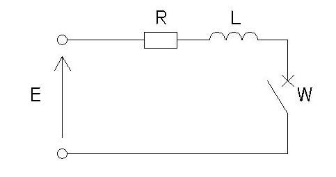
Fig. 1. DC circuit diagram – voltage source E; resistance R; inductance L and switch W.
Showed in 3, by changing the voltage between the electrodes slowly enough that for each measured value determined the concentration of charges, a plot of static voltage-current characteristics of the discharge can be made (Fig. 2).
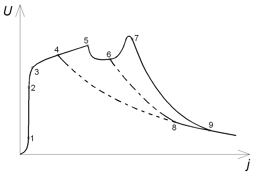
Fig. 2. Static voltage-current characteristic of the discharge.
Under the influence of the potential field of electrodes charges flow and changes the status of concentration of vapor charges:
 (1)
(1)
where: q – increase in concentration of vapor charges through natural ionization, αR – recombinant factor.
As the increase of the field strength the number of charges flowing to the electrodes increase, until all of generated vapor charges will flow to the electrodes. Current saturation occurs ,which density does not increase with increasing field strength (Fig. 2 – section 1-2). Further increase of the field will only increase the speed of charges (their kinetic energy). In step 2, the electron reaches the kinetic energy equal to the ionization energy so the first Townsend discharge occurs. Assuming that on a certain way electron with speed vek causes ionization of α gas molecules, the increase of vapor charges caused by collision ionization α in time dt reaches value:
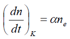 (2)
(2)
where: α – the first Townsend collision ionization coefficient, ne – electron concentration.
Bending the curve at point 3 (Fig. 2) is assigned to the collision ionization, the phenomena at the cathode, the cathode secondary electron emission and electron photoemission from the cathode. The section 3-4 is defined by a second Townsend coefficient. When the voltage reaches point 4 (Fig. 2) the ignition of spontaneous discharges occurs, which development is dependent on the circuit parameters and the state of gas. Townsend discharges (invisible) passing under the influence of an applied voltage to the spontaneous discharges may be variously developed:
1) Through the layer lightning discharges (sections 4-5-6), which suddenly (6-8) or gradually (sections 6-7) turn into arc discharge (section 9).
2) Directly (sections 4-8) in the arc discharge (section 9).
Static characteristics of the arc discharges is a part of the static characteristic U=f(i) at high currents range. This characteristic can have different course , but due to the occurrence of the initial discharges at very low current usually we use a simplified course (Fig. 3). The voltage Uz at a current i=0 is called the ignition voltage.
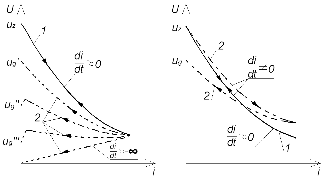
Fig. 3. Voltage-current characteristic of the DC discharge: 1 – static; 2 – dynamic.
With rapid changes in the current the state of concentration, temperature, heat, and the diameter of the arc does not correspond to the instantaneous current values observed in the steady state. Then the infinite number of dynamic voltage-current characteristics ua=f(ia) is observed. The course of the dynamic characteristics also depends on the rate of change of current. With decreasing current the voltage ua in ia=0 is called voltage arc quenching. Practically in all cases when the high current is switching off, the electric arc occurs. The essence of all kinds of electrical apparatus builders treatments, particularly contactextinguishing systems, is the design of devices to minimize the possible effects of the arc (heating chambers and contacts, contact material erosion). The main treatments, described in 2, are shorter arc burning and reducing the energy dissipated in the arc. Electric arc turns off when the current value is close to zero, but since DC naturally does not pass through zero, so its exclusion requires certain procedures that enforce forces obtaining zero value.
Among the methods can be distinguished: an increase in the resistance of the arc for example by lengthening the arc; develop oscillations in LC oscillator circuit; by injection of pulse of counter-current.
The overall condition of switch off the DC with starting value Iw can be defined as:
![]() (3)
(3)
where ia – the instantaneous arc current.
Considering circuit from Fig. 1 and applying Kirchhoff’s Law, the voltage can be written as:
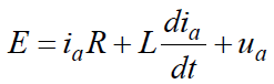 (4)
(4)
Where: ia – arc current, ua – arc voltage.
The main condition (3) is fulfilled when (4) will be written as:
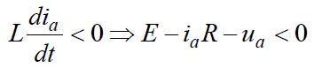 (5)
(5)
This can be interpreted graphically (Fig. 4), where dynamic characteristic of DC discharge is drawn with external characteristics of the circuit. Steady states occur at the location where both characteristics have common points, because in those points conditions below are fulfilled:
 (6)
(6)
In Fig. 4 the left plot shows the case, where the arc is burning in stable balance. The right plot of Fig. 4 shows the condition (3) and (5). In the case of effective switching off DC, the current is changing from Iw to 0 according to dynamic characteristic of arc.
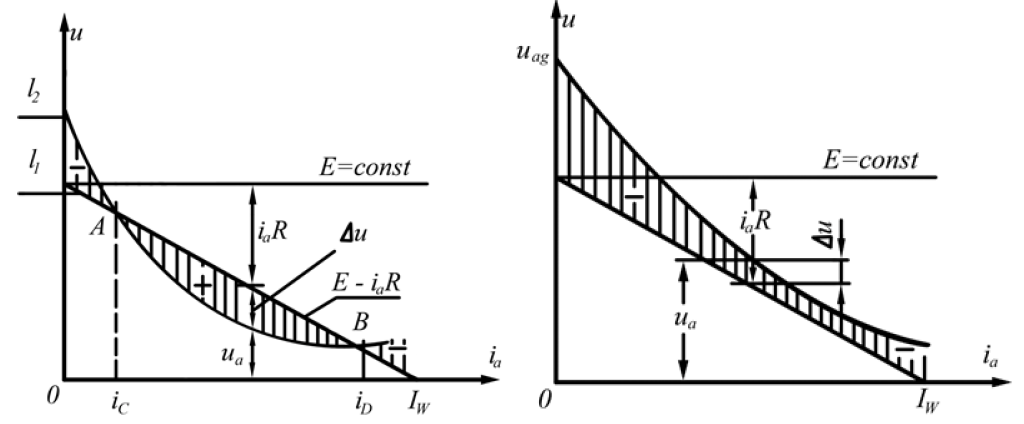
Fig. 4. Graphical interpretation of switching off DC by increasing the arc resistance – Dynamic characteristic of arc with external characteristics of the circuit [1].
Due to the nature of the exercises only switching off direct current by increasing the arc resistance will be presented and discussed in more detail.
Laboratory setup
The laboratory stand is located in the building of Warsaw University of Technology, Electrical Department in Warsaw, Poland. This exercise is one of six exercises performed during the course of Electrical Apparatuses for engineering course students on their 3rd year. The laboratory is mandatory for all that want to finish the basic course of Electrical Apparatuses.
The setup is build (Fig. 5) from a voltage source (rectifier), disconnector, two contactors connected in series (production of Apena), burden of adjustable resistance and adjustable inductance connected in series. Students sit in front of main board, so they can actually see all the processes occurring in the tests. Safety is maintained with use of emergency switch. Students work n groups of maximum 4 people, so that everyone can make observations and be a part of a lab team. The first connection is always made by the lab assistant, next are made in his supervision.
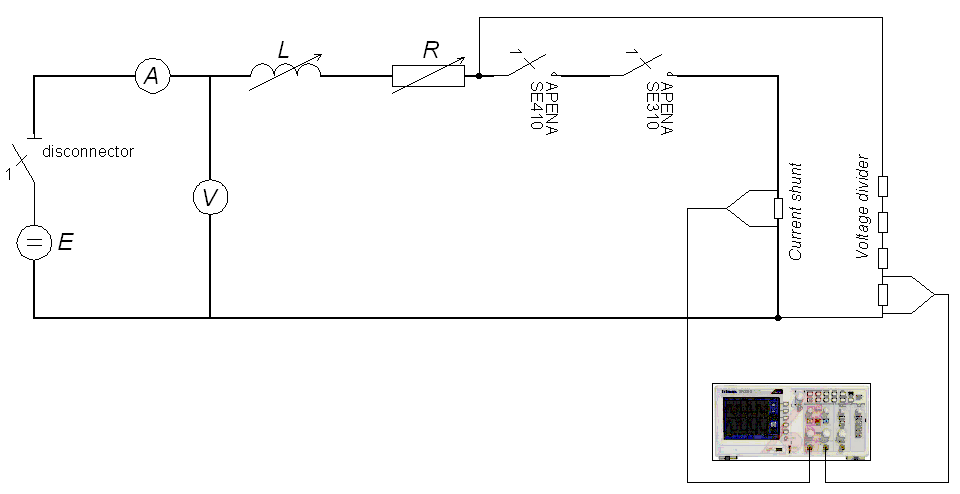
Fig. 5. Equivalent circuit of laboratory setup: R – resistance, L – inductance, E – voltage source (rectifier)
Discretionary standard PN-EN 60947-1:2010/A1:2011 in 4 with compatibility degree IDT with English standard EN 60947-1:2007/A1:2011 in 5 defines contactor as mechanical switching device changed over by different way than by hand, with only one resting position of movable contacts; capable switching on/off and conduction of currents in normal system operation and operating overload, as was described in 6. Electrical apparatus manufacturer establish and give the size and rated characteristics of the device for its intended use and the ability to work under certain conditions. In the laboratory setup two different contactors are used with nominal values of currents and voltages as in table 1. The main board of setup was shown on Fig. 6.
Table 1. Nominal values of voltage and current of used contactors
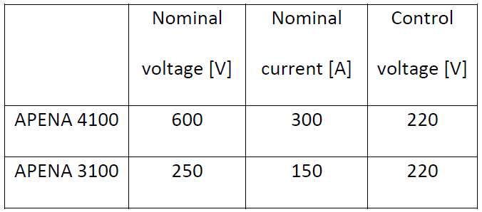
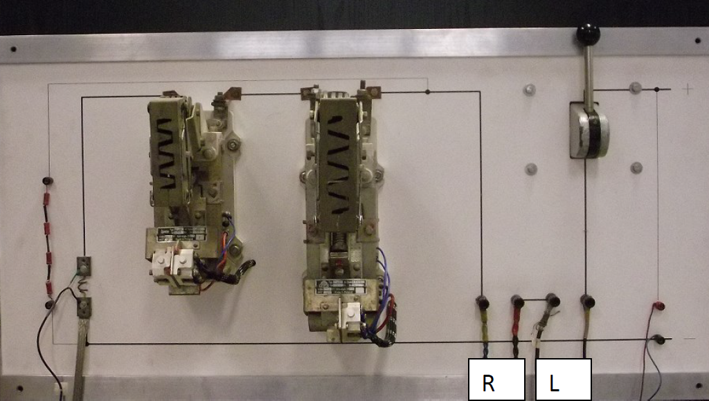
Fig. 6. The photo of main board of laboratory setup: R – resistance, L – inductance.
Used contactors are special with visible current path with coil made from this path (Fig. 7). At the time of contacts to disperse the magnetic field of the coil will blow arc to the extinguishing chamber. In this chamber the phenomenon of increase the arc occurs and also Increase the intensity of the heat dissipation from the arc, which leads to switch off.
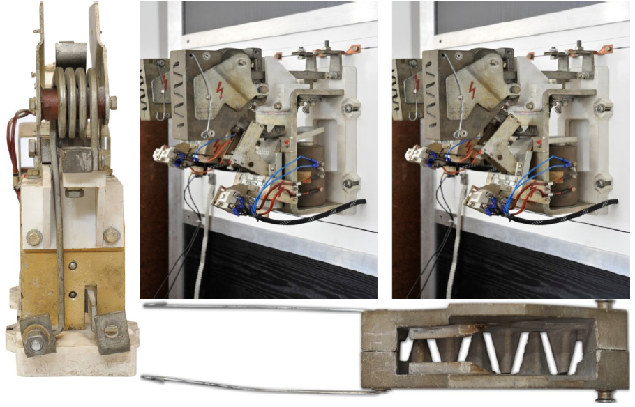
Fig. 7. Construction of the contactor: coil made from current path; contactor switched off and on; extinguishing chamber.
The values of currents and voltages are measured with amperemeter and voltmeter. The courses of voltages and currents are measured with use of oscilloscope through the current shunt and voltage divider. In respect to the safety obligations the exercise has the emergency switch.
Laboratory experiments
Students during the laboratory have to get familiar with the setup by drawing the equivalent circuit and the nameplates of all used devices. Next step is to measure voltage and current with voltmeter and amperemeter for all settings of inductance. The purpose is to show, that the inductance has no influence on steady state of direct current.
The second step is to examine the behavior of current and voltage during switching on the RL load. The control board is shown on Fig. 8 and is located at main board.
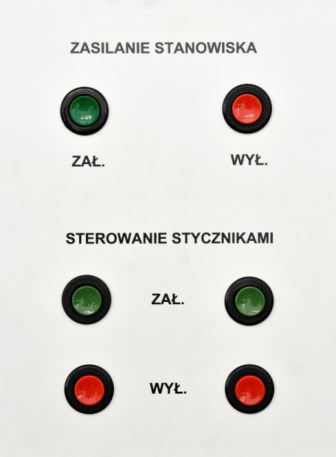
Fig. 8. Control board at the main board.
First two pushbuttons (Fig. 8 on the top) are for power supply to the laboratory setup. Two sets of pushbuttons below are for the contactors control. Student observe the courses of voltage and current on the digital oscilloscope TektronixTDS2001C for all five settings of inductance. The example courses are shown below (Fig. 9, 10).
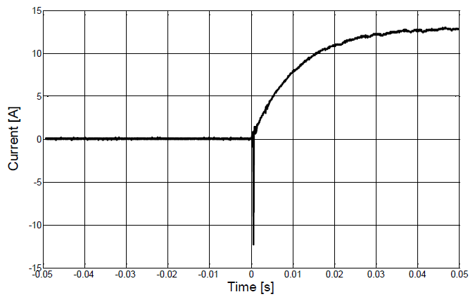
Fig. 9. Current versus time during switching on the RL load.
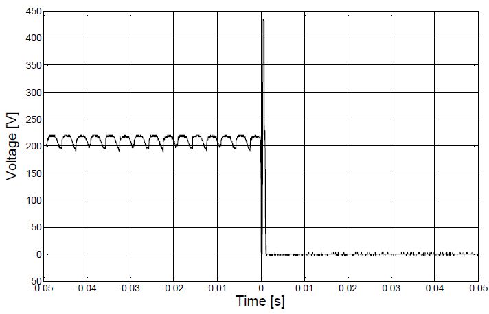
Fig. 10. Voltage versus time during switching on the RL load.
Next step is is to examine the behavior of current and voltage during switching off the RL load. This part has a purpose to watch the courses of measured values and then to draw dynamic voltage-current characteristic. The example courses are shown below (Fig. 11, 12).
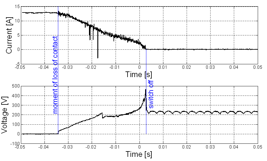
Fig. 11. Current and voltage versus time during switching off the RL load.
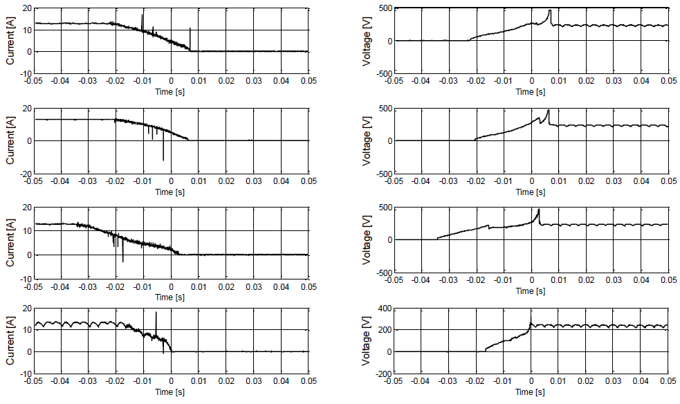
Fig. 12. Examples of current and voltage versus time during switching off the RL load.
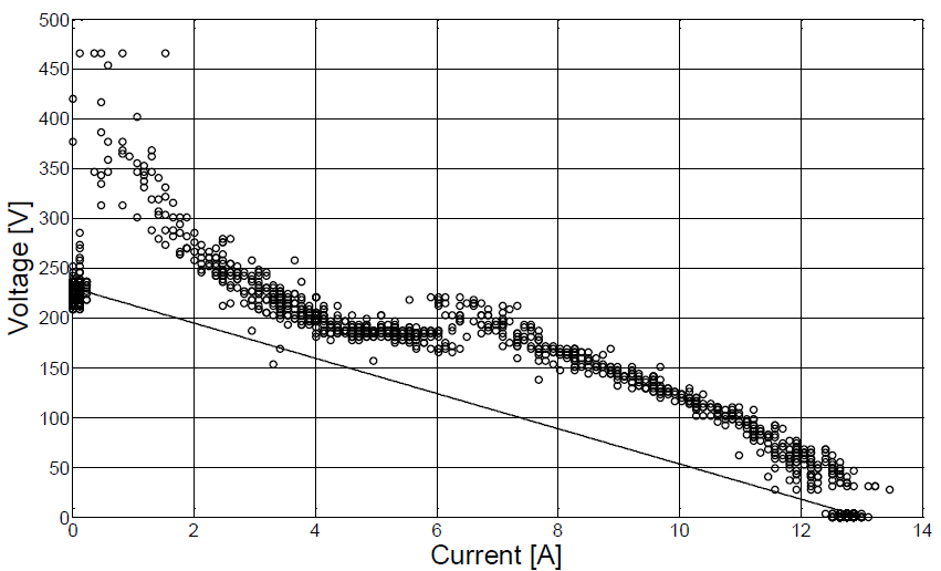
Fig. 13. Dynamic characteristic of arc (plot with “o”) with external characteristics of the circuit (line).
Students observe different values of overvoltage depending on the different inductance. Their task then is to calculate unknown parameters R, L and upon this conclude about the influence on current and voltage on those parameters. At home students can prepare a report from laboratory. One of the main elements that have to be in a report is a dynamic characteristic of arc. The example characteristic is shown on Fig. 13.
To successfully switch off direct current, the dynamic characteristic of arc must be placed over the external characteristics of the circuit. There is a possibility to have a situation with static equilibrium where both characteristics has one common point.
During one of the tests of laboratory setup authors made photos from fast camera when switching off. The results are shown in Fig. 14.

Fig. 14. Photos from fast camera during switching off
Evaluation of exercise
In general it is observed that the educational value of this exercise for students is high because they have the opportunity to experience a live electrotechnics. The other alternative is to create a simulation program i.e. in Matlab or in Simulink, but in that option students could not fully understand the problem. Simulation also cannot give opportunity to operate real oscilloscope, see how the contactor works, and find how voltage and current can be measured. Students usually have a negative opinion about electric arc, as a phenomenon that creates additional heat and electromagnetic tension. Here they can observe how the electric arc reduces current to zero decreasing overvoltages during interruption. Showing them electric arc in contactor without extinguishing chamber can confirm that opinion. Without proper explanation of the theory and comparing it with measurements it can be fixed by students.
After each year students can take part in questionnaire about the laboratory exercises. Most of them really appreciate especially switching off direct current with contactors. In the majority opinion this exercise gives them knowledge about switching electric arc and the influence of inductance on DC circuits in real conditions.
The main educational aspects from this exercise are:
– understanding the necessity of existing switching electric arc,
– observe influence of inductance on current during switching on,
– observe overvoltage due to existing of inductance,
– learn how to use an oscilloscope.
References
1. Z. Ciok, „Transients In Power Systems”, WNT, Warszawa 1983.
2. L. Van der Sluis, „Transients In Power Systems”, John Wiley & Sons, LTD, 2001
3. Jerzy Kryński, „Electrical Apparatuses”, PWN 1964
4. E. Kuffel, W. S. Zaengl, J. Kuffel. High Voltage Engineering, Newnes, 2000.
5. PN-EN 60947-1:2010/A1:2011
6. EN 60947-1:2007/A1:2011
7. G. G. Seip et al., „Electrical Installations Handbook”, Siemens AG, John Wiley & Sons, 1987
8. CIGRE Working Group B4-52, “HVDC Grid Feasibility Study”, Brochure 533, April 2013
9. J. Bird, “Electrical circuit theory and technology”, Newnes 2003