16 Determination of short-circuit currents (fin)
The goal of the task is familiarising the students with the problem of short-circuit currents calculation in electric power transmission network. Fault calculations are performed both at the stage of design and exploitation of electric power systems. In the phase of design they serve mainly for the choice of substation switchgear and other devices, lines and cables, and during exploitation for the selection and setting of electric power devices of protection systems. Short circuit calculations are performed making a series of assumptions simplifying these computations:
- loads are neglected – it is assumed that the system is in the state without current for a moment before the fault,
- magnetising reactance in transformers and line earth capacitance are neglected,
- element resistance is disregarded, particularly in transmission networks of the highest voltages,
- transformation ratio is taken into account in an approximate way.
Above simplifications and the entire methodology of computing characteristic values for short circuits are contained in Polish standards PN-74/E-05002 and PN-9*/E-05002.
Calculation of a three-phase fault current in a simple electric power system
Given simple transmission system consisting of a generator, unit transformer and transmission line as in Fig. 1.
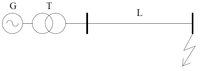
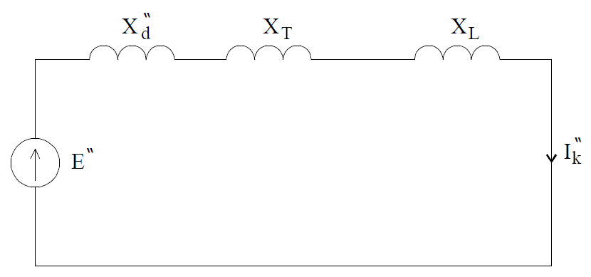
In this system we have to calculate initial short circuit current at three-phase fault in the end of the line leading out the power from the power plant. For this purpose an equivalent scheme have to be created, as in Fig. 2.
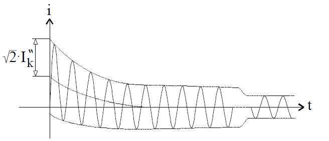
Instantaneous curve of a short circuit current as a function of time is presented in Fig. 3.
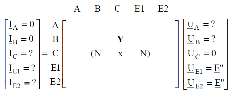
Generators in the first moment of fault are represented by subtransient reactance, transformers and lines by their reactance. Initial fault current which flows in the system is:
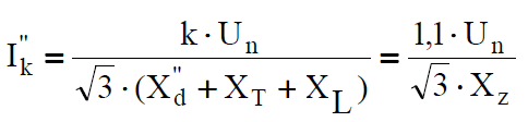
where Xz short circuit equivalent reactance of the loop – in this case it constitutes series connection of generetor, transformer and line equivalent reactance; coefficient k is the result of that, that if we want to keep voltage at the customer’s on the preset level the voltage in generators must be slightly higher. In practice k = 1 .1 is taken.
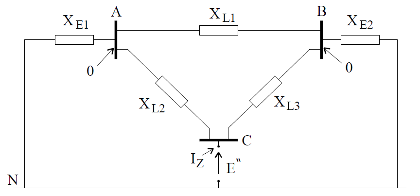
In electric power system, as in Fig. 4, consisting of two power stations operating on common transmission network, calculation of the three-phase fault current on the busbars in substation C consists in creation of equivalent network as in Fig. 5.
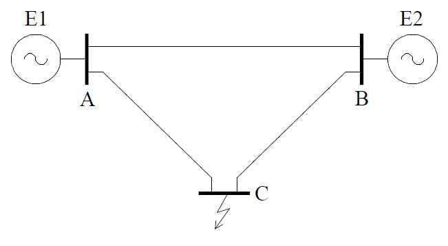
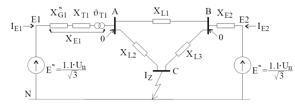
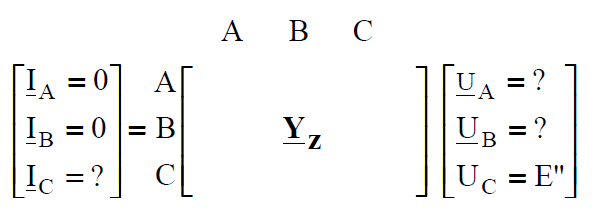
In this scheme branches XE1 and XE2 constitute resultant reactance of generator and transformer units working on common busbars. For a three-phase fault on the busbars of substation C the initial short circuit current is calculated from the formula (1); in this case the short circuit reactance is the result of transformation of the scheme from Fig. 5. to single equivalent reactance seen from the place of fault. The delta of line reactances should be changed into equivalent star, we get two series connections, which after ‘reduction’ give parallel connection of two reactances. In the end we will receive the system with parallel connection and after adding these reactances we will get resultant reactance of the system – short circuit reactance. For a fault on busbars A the calculation of short-circuit reactance will follow quite different algorithm – delta-star transformation need not to be employed, and in the first step we should connect reactances XL2 and XL3 and the resultant reactance in parallel with reactance XL1, and then in series with reactance XE1 and in the end in parallel with XE2. The method of ‘manual reduction’ of the network to a single reactance is labour-consuming and not acceptable for real electric power systems. We should apply matrix methods – the method of nodal potentials. For the electric circuit in Fig. 5 constituting equivalent scheme of an electric power system, we can write matrix equation resulting from the nodal potentials method: I = Y*U and in developed form it is:
We have received a matrix equation constituting linear system of five equations with five unknowns. Solving this system we will receive wanted current and voltage values in electric power network in the first moment of fault on busbars C. We should notice, however, that unknown values are present on both sides of the matrix equation – both in the vector of unknowns and in free terms. So before starting to solve this system we should order it. The system of equations (6.3) will change very little for example when short-circuit is on busbars A – matrix Y will remain the same while elements of vectors I and U will change.
According to the Thevenin’s theorem the electric circuit from Fig. 5. is equivalent to the electric circuit from Fig. 6. This scheme was created as a result of shorting the sources in the scheme in Fig. 5 and putting electromotive force E” in the place of fault (there is non current state before the fault, all voltages in the network are equal to E”.
Electric circuit like in Fig.6.6. may be solved by the method of nodal potentials. We can write the matrix equation:
I = Yz*U
which in developed form is:
We have received linear system of equation of the third degree with three unknowns, which is now a little bit easier for solving, and after calculation of inversion of matrix YZ we can write the following impedance equation:
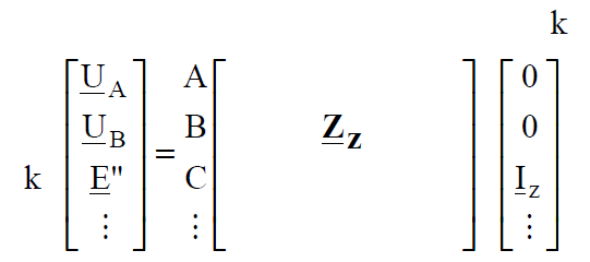
Where Zz = Yz-1 is called short-circuit impedance matrix.
Equation (5) has more general character. For arbitrary large electric power network the equivalent scheme like in Fig. 6. will have similar form, and in matrix equation (5) and (6) number of rows and columns will increase. It should be noticed that the vector of nodal currents will have one non-zero element, because only in the node in which short-circuit exists the current is injected to the electric circuit; This current flows in different directions through the network and behind generators reactances (shorted EMF) it flows to the ‘earth’ and comes back to the place of fault. According to the calculation of matrix product we can compute E” by multiplying the k-th row of Z matrix by the column of currents:
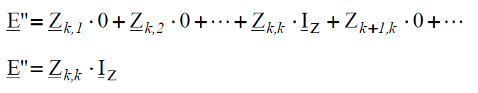
and from here we calculate IZ:
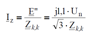
We have received a formula analogic to formula (1) for fault current calculation by the method of ‘reduction’ of the circuit to the resultant reactance. So we can say that the diagonal element Zk,k from the short-circuit matrix corresponding to the given node is equal to the short-circuit impedance seen from this node. So ‘reduction’ of the circuit to the resultant reactance was replaced by the calculation of admittance matrix corresponding to the short circuit scheme of the network from Fig. 6. In this formula the electromotive force was introduced on purpose in imaginary axis (with operator j), so the currents lay in real axis, because usually fault calculations are performed with neglected resistance.
Basic quantity which characterises short-circuit current parameters is short-circuit power,
Sz = √3 Un * IIzI (8)
which is the base of switchgear choice and short-circuit strength of electric power system.
The flow of current in any branch of electric power system connecting nodes i – j can be calculated on the base of Ohm’s law:
From the impedance matrix equation (6.6) voltage in arbitrary i-th node, according to the principle of matrix product calculation is:
Substituting (6.10) to (6.9) the current in arbitrary branch is calculated from the following formula:
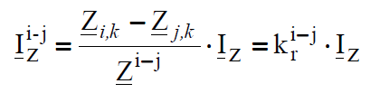
where Zi,k, Zj,k are the elements of short-circuit matrix Z, and Z i-j is the impedance of the branch, in which fault current flow is computed. Coefficient kri-j is the coefficient of short circuit current distribution – it determines what part of the fault current flows through the branch joining nodes i-j.
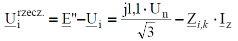
Formulae (7 .. 11) enable to calculate short-circuit quantities basing on network equivalent scheme (fig .6) after Thevenin’s method application . This is somehow fictional model, but according to the Thevenin’s principle it is equivalent to the real circuit, in which currents from generators flow through the network to the place of fault. Therefore in the real network (Fig. 4) the directions of fault currents are opposite to the directions of currents computed from(6.11). The arrangement of voltages in the real network (Fig. 4, 5) is different from one after Thevenin’s theorem application (Fig. 6). It is easy to notice that the voltage, for example Ui in the network in Fig. 6, and computed on the base of the formula (10) is noting else like the difference of voltages between the node where EMF is supplied and the given i-th node in the network from Fig. 5. Therefore we receive voltages in the real network computing:
Computation of phase currents and voltages during short-circuits
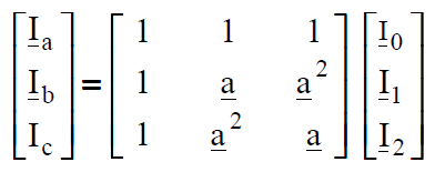
Three-phase faults are met very rear in practice and they are caused, for instance, by switching mistakes – switching-on a line from which grounding was not disconnected after the repair of this line had been finished. The most frequent faults are phase-to-earth faults. And so practically we must, for example, for the goals of protection system setting calculate current and voltage values during phase-to-earth and phase-to-phase faults – unsymmetrical short-circuits. Unsymmetrical short-circuit it is a state of asymmetrical load of a three-phase system and the method of symmetrical components for analyses of such states is used. The method consists in that, that a three-phase electric circuit, both at symmetrical and asymmetrical load may be replaced by three separate electric circuits: for zero, positive and negative sequence components. At symmetrical load of the three-phase system zero and negative sequence components of currents and voltages have values equal to zero, and in the state of asymmetry values different than zero. If, for example, current symmetrical components are given then the phase components are calculated by multiplying the previous ones by the transformation matrix S-1:
 (13)
(13)
According to the relation (13) currents at the place of fault, currents flowing in network branches and nodal voltages are transformed.
So we should state that in fault current calculations (symmetrical and unsymmetrical) we ought to create three separate network equivalent schemes: for zero, positive and negative sequence components – calculate three separate short-circuit matrices. The calculations are performed separately for each scheme, and in the end zero, positive and negative sequence components are recalculated on phase components. It is assumed that the reactances for positive and negative sequence components are the same, but reactances for zero sequence component sufficiently differ in values from positive sequence reactances.
Short-circuit element models of electric power system elements
In fault calculations the resistance of shunt branches elements s neglected, so an electric power line for three-phase faults is represented by reactance for positive sequence component, the same as for load flow calculations.
Reactance for the positive sequence component of the transmission network is the same like in load flow calculations, in catalogues X’ [ohm/km] is given. Reactance X0 for the zero sequence component is given in the cathalogue data of a transmission line as the ratio of its value to positive sequence reactance – for electric power lines this ratio is about 3. two-terminal network X, and curents flowing during the short-circuits in the line are calculated according to the formula (9) or (11).
Elecric power transformers are three-phase transformers which windings may be connected in delta or star. When the winding is connected in star its neutral point may be grounded or not. From the other side connection in delta is characterised by that, that it ‘contains’ current third harmonic, and during unsymmetrical faults it contains the zero
sequence component of the current. In Fig. 7 a comparison of a transformer equivalent scheme for load flow calculations (steady states) with a scheme for short-circuit calculations has been presented. The scheme for the zero sequence component enables to model various arrangements of transformer connections by the change of zero sequence reactance values XG0, XD0 and XP0. It is quite comfortable scheme, because topologically it enables to create
electric power network model for zero, positive and negative sequence components of the same topology, and differing by the values of reactances.
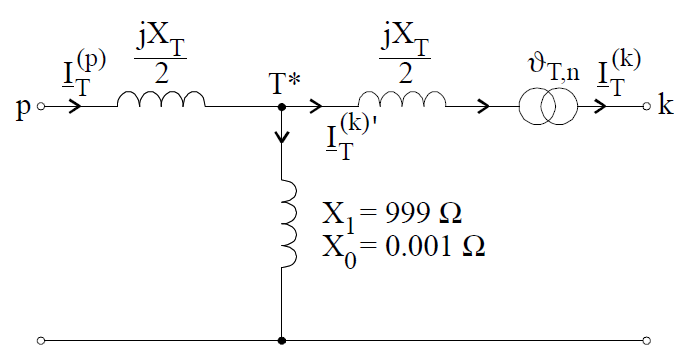
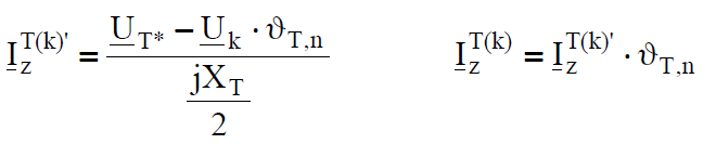
As it results from a transformer equivalent scheme for fault calculations there may be computed three currents in the transformer: from the side of initial node (p), from the side of final node (k) and a current in a shunt branch. The current in the shunt branch is not important from the practical point of view. The current from the initial node side is computed from the formula (9) or (11) like for ordinary branch representing a transmission line – we should remember that the voltage in the node marked by T* in Fig.6.7 should to be calculated and reactance XT/2 taken into account. On the other hand the fault current flowing through the transformer from the side of final node is calculated with regard to turn-to-turn ratio:
For transformers with zero hour shift the ratio is a real number, but at connections of the type star-delta we should additionally take into account hourly shift. Transformers present in the transmision network 400kV/220kV/110kV are usually autotransformers of zero hourly shift.
Short-circuit scheme of a generator-transformer unit constitutes equivalent reactance, like in Fig. 8.
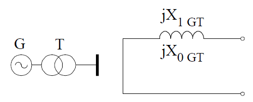
The reactance of a generator-transformer unit is calculated similarly as transformer reactance for load flow calculations from the following formulae:
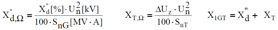
Reactance for zero sequence component X0GT is usually assumed to be 0.8XT.
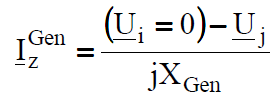
According to the equivalent scheme construction (Fig. 6) for determination of short circuit matrix the current flowing through the branch modelling generator-transformer unit may be computed from the formula (6.9), but we must remember that one of the voltages is equal to zero:
Computational example
Calculate short-circuit currents in the network in Fig.6.8. (an example for load flow calculations)
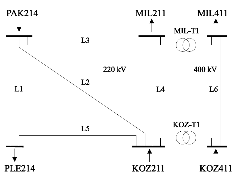
It is the same network like in the example of load flow calculations. Parameters of this network and basic data both for load flow and short-circuit calculations are given in task 5.
Performance of short-circuit calculations by program PLANS
After starting the program we should read in the network data to the operational memory by choosing function Plik->Czytaj dane (File->Read data) from the menu. A window for indicating the file containing network data will appear on the screen. Exemplary data are in the file named: przyklad.ien (example.ien). Reading in of data is signalled on the computer screen by corresponding information window. Read in network data may be viewed and edited in option: Dane->Węzly, Dane->Galęzie (Data->Nodes, Data->Branches). After making sure that the data are correct short-circuit calculations may be started by choosing the function: Obliczenia->Zwarcia w sieci (Calculations-> Short-circuits in the network). A window will appear on the screen in which all results of short-circuit calculations will be
presented. The menu of the program will also change. In the group DaneZwar there are commands enabling data viewing (Reaktancje galęzi – model zwarciowy sieci) (Network reactances – short-circuit network model). Group Oblicz (Calculate) contains commands enabling calculation performance. We can determine and watch short-circuit admittance matrices and short-circuit impedance matrices for positive and zero sequence components (Y1
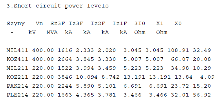
_zwar, Z1_zwar, Y0_zwar, Z0_zwar). In this group command Zwarcie w węźle (Short circuit in node) computes currents and voltages in the place of fault for chosen node and type of fault, first in symmetrical components and then in phase components. In this command graphical visualisation of currents and voltages in the place of fault is possible. Command Oblicz->Prąd zwarcia w galęzi (Calculate->Short-circuit current in branch) computes short-circuit current on the edges of chosen branch, and then short-circuit currents during the fault in the place of fault chosen earlier in command Zwarcie w węźle (Short-circuit in node). Command Oblicz->Poziomy mocy zwarcia Sz (Calculate->Short-circuit power levels Sz) calculates values of three-phase fault powers, three-phase fault currents, phase-to earth and phase-to-phase fault currents for all network nodes.
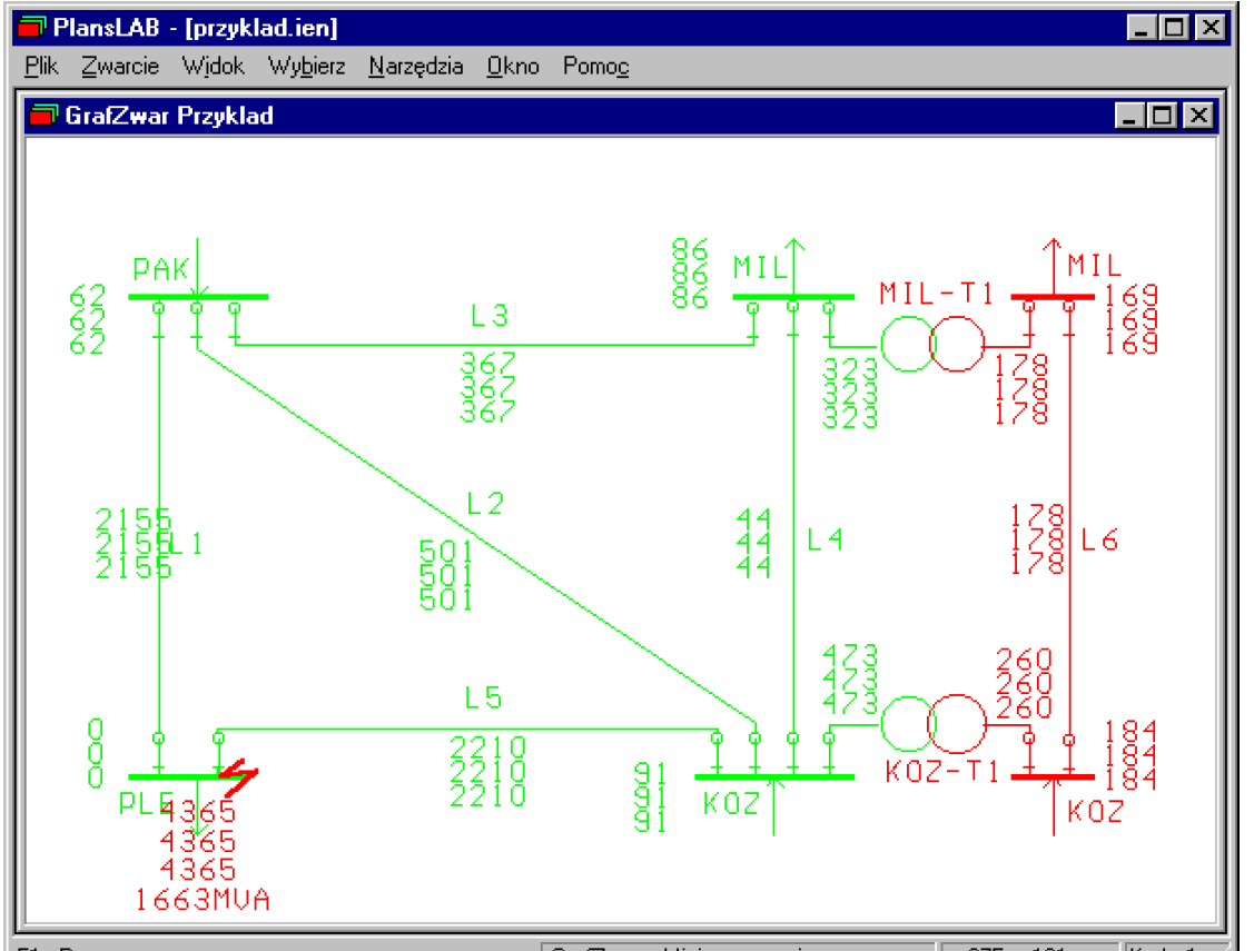
The best way of analysing short-circuit current distributions and voltage levels is to use graphical mode in option GrafZwar. Menu containing two possibilities will appear on the screen: Schemat or Węzeł.
After choosing network scheme a picture of the scheme will appear, on which we can simulate various kinds of short-circuits choosing command Zwarcie->Miejsce zwarcia (Fault- Place of fault), then, using mouse, we should point any element in the picture. After pointing the place of fault and choosing the type of fault the program will perform short circuit calculations, and it will show results on the network scheme like in Fig. 9.- short circuit in the network for a three-phase fault on busbars in substation PLE on a computer model.
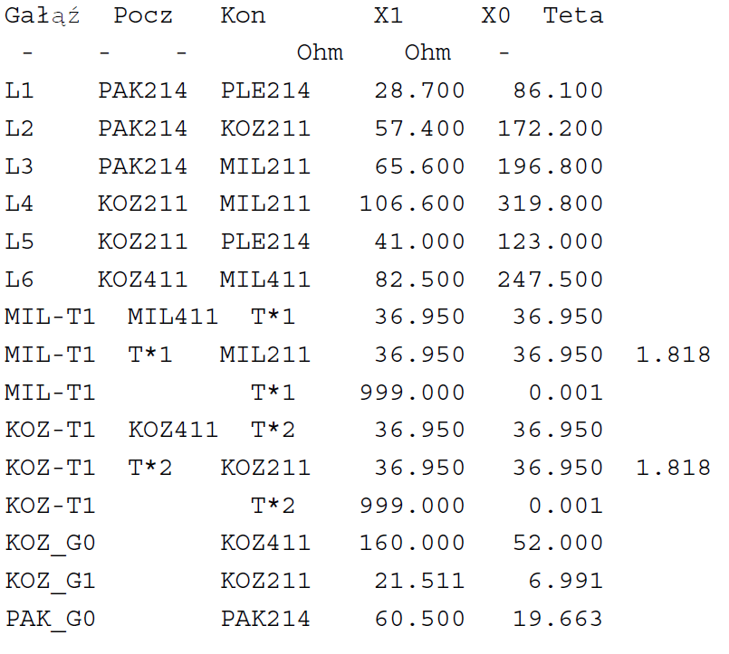
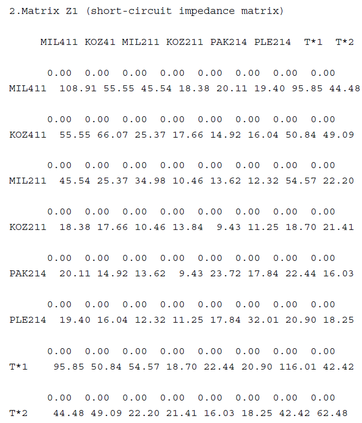
Short-circuit calculation results in the form of computer listings received in the option Sprawozdanie (Report) contain topologic and reactance parameters of the transmission network – short-circuit scheme in the numerical form. Then short-circuit impedance matrix is printed and the short-circuit voltage levels in the nodes of electric power network.
Elaboration of calculation results
1.Network equivalent scheme for short-circuit calculations
Test No. 2
2. For a three-phase fault in the node:
PLE211
Calculate:
a) currents flowing during the short-circuit in the line :
L3
b) currents flowing during the short-circuit in the transformer:
KOZ-T1
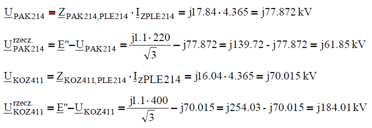
c) voltages in the nodes:
PAK214, KOZ411
Branch impedances and short-circuit impedance matrix data are given.
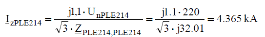
Calculation of currents and voltages during the three-phase fault in the node PLE214:
The current in the place of fault:
The current in line L3 (in the network after application of Thevenin’s theorem):
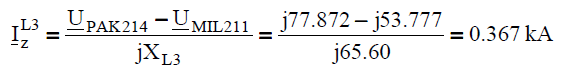
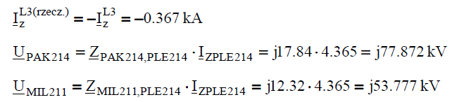
The current in line L3 in real network:
The current in the transformer KOZ-T1 on the side of 400kV voltage (after Thevenin’s theorem):
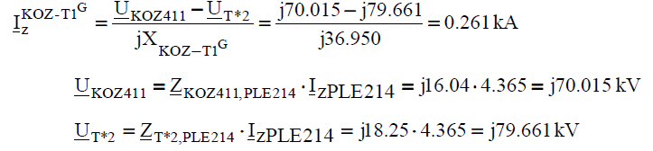
The current in the transformer KOZ-T1 on the side of 400kV voltage in the real network:
The current in the transformer KOZ-T1 on the side of 220kV voltage (in the network after application of Thevenin’s theorem):
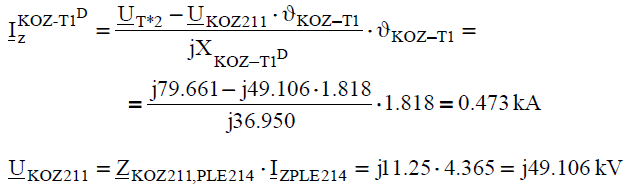
The current in the transformer KOZ-T1 on the side of 220kV voltage in the real network:
Voltages in the nodes PAK214 and KOZ411 during the short-circuit in the node PLE214: