
12 Reactive power compensation (fin)
The goal of the laboratory training is to investigate the reactive power compenstation problem.
1. General information
Alternating current receivers consume real energy from the EPS, which is then converted into useful energy and heat losses. Apart from real energy reactive energy occurs in the grids. It does not carry out any work but conditions the correct operation of these receivers.
If the demand uses inductive reactive power from the grid, it is often referred to as reactive power load, whereas if the demand consumes reactive capacitive power, it is often understood as reactive power generation. Capacity and inductive reactive power have opposite signs. Reactive power demand in electric power system occurs when the load needs magnetic flux to work, whereas capacity reactive power occur when the load generate electric field.
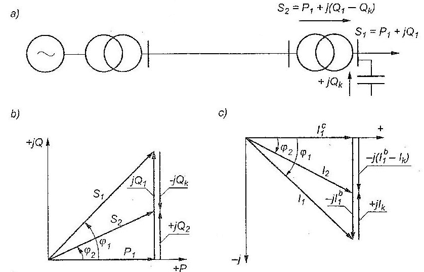
Half of the reactive power consumption is in EPS (highly loaded lines, transformers). The rest of the power is mainly consumend by motors. To supply loads with reactive power we may either send it from the power plant (via EPS) or compensate it locally (figure 1).
Reactive power sources
The following sources are used for inductive reactive power generation:
– synchronous generators in electric power plants,
– capacitor banks for reactive power compensation (connected in parallel)
– controlled reactive power sources – so called FACTS technology elements: SVC and SVG
(Statcom),
– synchronous compensators (rarely because of costs),
– synchronous motors (and sometimes asynchronous synchronized) – also rarely.
Additionally reactive power is generated – in natural way – by electric power lines because of their capacity. ln very high voltage lines the generation of inductive power is very high, and at the flow of powers less than natural power – the loading power ‘is greater than inductive power losses in overhead lines of rated voltages 750 kV (and greater) compensation of opposite sign is used – permanent shunt reactors are installed (every a few tens of km of the line).
The cost of power transmission in networks is very high (150% – 300% of production costs). Therefore, from an economic point of view, the production of reactive power and its shipment to customers is not viable. A much cheaper solution is to use local energy sources, preferably as close to the recipients as possible.
Negative effects of reactive power
Normally active and reactive power sources are situated far from the places of their consumption. Then the power is transformed many times and sent to the consumers through the network. As it was mentioned, the transmission of reactive power is cost ineffective. Low power factor (cosφ = P/S) leads to negative effects such as:
– reduction of generators real power capacity, generator power is limited by the current flowing in annature winding, the driving turbine is fitted to generator real power so to its nominal power factor. Thus if generator works at less than nominal cosφ – the stator thermal capacity makes it impossible to use the full active power of the unit. Apparent power also decreases at small values of power factor because armature reaction increases, which reduces its electromotive force. This influence may be compensated by the increase of field current, but in such a way that the generator rotor will not be overloaded.
– Reduction of lines and transformers transmission capacity is determined by the current causing permissible heating, and as a consequence permissible line sag. The flow of reactive power causes necessity of reduction of transmitted real power and this reduction is directly proportional to the power factor. If for example a transformer of rated power 1000 kVA at a power factor of 0,7 may be loaded by a real power of 700 kW, then when the cos φ rises to 0,85 its real power load may be increased to 850 kW.
– Increase of electric energy generation and transmission losses, Active power losses in power system elements depend on the state of load and they increase considerably when receivers power factor decreases. Real power losses are expressed by the formula 1, so inversely proportional to the square root of power factor.
ΔP = 3I2R = (S/U)2R= (P2/U2cos2φ)R (1)
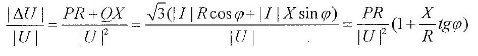
– Increase of voltage drop – voltage drop is linearly dependent on tgφ and the ratio X/R, which is constant value for given network element (shunt G and B – neglected). Voltage drop at decreasing power factor makes voltage regulation difficult and has negative influence on receivers work.
Describtion of laboraty stand
The stand consists of feeding, controlling and measuring part, induction motor, braking device and capacitor battery for compensation. Schemes of control and measuring systems are placed on the frontal panel of the laboratory stand. Main measuring system is used for investigation of asynchronous motor characteristics in steady and transient states and for measuring load symmetry of capacitor battery and measurement of capacitor capacitance by technical method. Figure 2 presents the front panel of the laboratory stand.
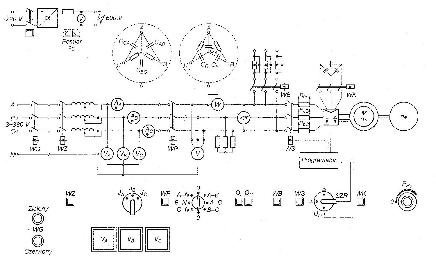
The investigated asynchronous motor parameters are as such Pn = 1100 W, Un = 3×220/380 V, In = 4,3/2,5 A, cosφn = 0,82, n = 1420 r.p.m. It is connected to another machine (generator) and the generated power is transfered to electrical power and then dispared in resistance (PHe).
During the laboratory classes students shall obtain various characteristics of the motor and draw conclusions about real and reactive power consumption. The following mode are going to be performed:
- cosΦ (PL)- Motor windings connected in star, without capacity banks at constant voltage V=127V
- cosΦ (PL)- Motor windings connected in delta, without capacity banks at constant voltage V=127V
- cosΦ (PL)- Motor windings connected in delta, with capacity banks at constant voltage V=127V
- cosΦ (V)- Motor windings connected in delta, without capacity banks at constant power P = 1100 W
- cosΦ (V)- Motor windings connected in delta, without capacity banks at constant power P = 700 W