
4 Electric Energy Quality
ELECTRIC ENERGY QUALITY
The correct functioning of electricity receivers can only be ensured if the quality of electricity supplied to the terminals of the receivers is adequate.
Basic electric energy quality parameters are:
– frequency,
– voltage level,
– voltage fluctuations,
– voltage symmetry,
– voltage harmonic distortion factor,
– reliability of supply.
Required frequency is 50 Hz (or 60 Hz) with maximum deviation:
• -1 % to + 1 % during 95 % of a week
(from 49,5 Hz to 50,5 Hz),
• -6 % to + 4 % during 100 % of a week
(from 47 Hz to 52 Hz).
According to The European standard EN 50160 the limits for voltage disturbances are:
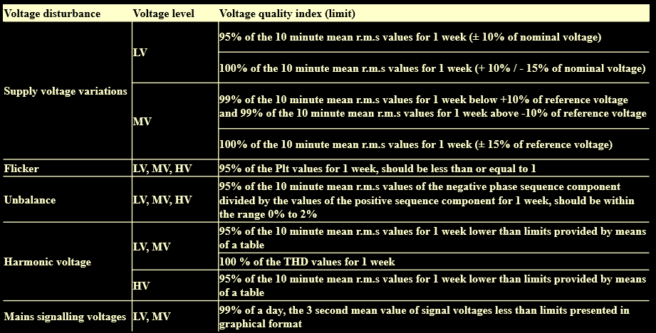
REQUIREMENTS
voltage fluctuations – during 95% time of every week long-term light flickering index Plt in successive twelve periods of time should not be greater than 1.
where – Psti long-term light flickering index (measured through 10 minutes)
Voltage Symmetry – in every week 95% from the set of 10-minutes average effective values of negative sequence component of supply voltage, should be in the range:
0% to 1% for 110kV, 220kV and 400kV networks
0% to 2 % for medium voltage (MV) and low voltage (LV) networks.
Voltage Harmonic Distortion factor of supply voltage THD
should not for the set of 95% 10-minutes average values be greater than:
3% for 110kV, 220kV and 400kV networks
8% for medium voltage (MV) and low voltage (LV) networks..
Reliability of Supply – the duration of a single emergency interruption in the supply of electricity and the total duration of emergency interruptions in one year should not be longer than:
a) the value specified in the sale contract of energy for customers fed from MV, 110kV, 220kV and 400kV networks,
b) 24 h single and 48h annually for customers fed from LV network.
Receivers themselves may also cause decreasing of electric energy quality delivered to their terminals. Thus, so called restless consumers, i.e. receivers with frequent, high and rapidly changing currents, e.g. frequently started asynchronous motors and non-linear receivers, which are the source of higher harmonic currents, affect the quality of energy supplied to the receivers.
The lecture will focus on issues related to voltage quality, voltage and current distortions, and power supply reliability. In addition, we will consider the concepts of: customer, load and energy receiver.
CUSTOMERS, LOADS AND RECEIVERS OF ELECTRIC ENERGY
Receiver of electric energy – a device, machine or apparatus converting electric energy into energy needed by the customer. Examples of receivers are: engine, light bulb, heater.
Electricity Load – electricity or energy drawn continuously or intermittently by a receiver or a group of receivers. An example of load is the power consumed by the receivers installed in the apartment block, or the power consumed by the receivers in the factory powered from the MV mains using its own transformer station.
Customer of electric energy – a natural or legal person who owns electric energy receivers constituting one or more electric energy loads.
Customers may, in general, bedivided into three groups:
– industrial customers,
– urban customers,
– rural customers.
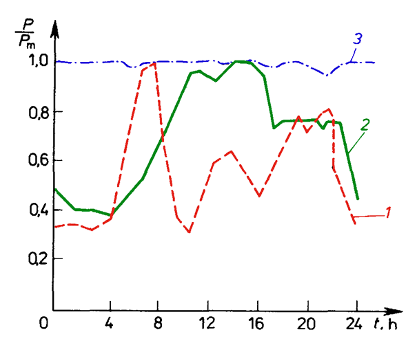
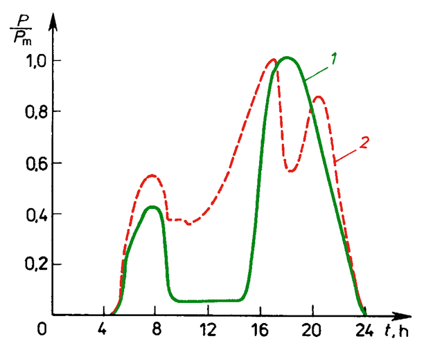
Each group of receivers, customers and loads has its characteristic load duration curve: 24 hour-, weekly-,monthly- and annual-curve. This curve presents changes of power consumed by a receiver or a customer during the given period of time. Usually average 15-minutes values of power are used. Continuous curves plotted in the graphs represent average powers.
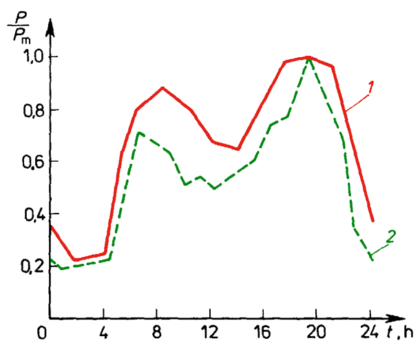
The system load duration curve is the result of adding load duration curves of individual customers. Typical load curves for industrial customers during the week are shown in Figure 3.1. and urban and rural load curves on a weekday in winter in Figure 3.2.
CHARACTERISTICS OF RECEIVERS
Electric power grid feeds various types of receivers used for different purposes. They can be classified from different points of view, but the most commonly used is a breakdown related to their function:
– electric motors,
– electric sources of light,
– electro-thermal devices
– other receivers (their share in energy consumption is negligible).
Taking into account the type of feeding current, the receivers may be divided as follows:
– alternating current receivers (three-phase or single phase) of frequency 50 Hz,
– alternating current receivers of other frequency, for example induction furnace,
– direct current receivers, for instance galvanic devices.
Taking into account nominal voltage value, the receivers may be divided into:
– receivers of nominal voltage higher than 1000 V, for example 6 kV motors,
– receivers of nominal voltage lower than 1000V, for example. 230V, 400V, 500V and 660V,
– low voltage receivers of safety voltage 24V for operation in compartments with high possibility of electric shock.
Taking into account load symmetry, the receivers are divided as follows:
– receivers loading electric network symmetrically (almost all three-phase receivers),
– receivers loading electric network non-symmetrically (all single phase and two-phase receivers and some three-phase receivers).
Taking into account character of work, the receivers are divided as follows:
– receivers with constant load, for example resistor furnaces without regulation, bulbs, ventilators,
– receivers with variable load, for instance arc furnaces, lift motors, motors driving compressors.
Taking into account power drawn from the network at at start-up, the receivers are divided as follows:
– receivers which power at start is more or less equal to the power at normal work, for example resistor furnaces, bulbs,
– receivers which power at start is much higher than the power at normal work, for instance motors.
Taking into account the power factor, the receivers are divided as follows:
– active power receivers, for example resistor furnaces, bulbs,
– receivers of active power and reactive inductive power, for example asynchronous motors, reactors, induction furnaces,
– receivers of active power and reactive capacitive power, for example phase shifters,
– receivers of reactive capacitive power, for example capacitors.
INDUSTRIAL CUSTOMERS
The electricity consumers used by industrial consumers differ in terms of type, construction, parameters, purpose, nature of power consumption and environmental impact. The main group of receivers are induction and synchronous motors, as well as electric arc, induction and arc-resistance furnaces. Devices consuming energy by means of rectifiers constitute a special group of receivers (electrolysers).
NON-INDUSTRIAL CUSTOMERS
This group includes urban and rural customers. Lighting, heating and motors are the primary receivers in both urban and rural households.
An example of a 24-hour load duration curve for household lighting appliances and electric cookers is shown in Figure 3.3.
VOLTAGE QUALITY
Voltage is one of the most important parameters determining the quality of electricity. The value of voltage can be different in different points of the network, it can differ even in individual receivers installed at one recipient. Electricity receivers are designed to work most efficiently at a voltage close to the rated voltage of the network.
Voltage level it is the effective value of voltage U in the specified network point, measured during specified period of time.
Voltage deviation from nominal value in the specified network point is the difference between the effective voltage value U at this point of the network, in given period of time, and nominal voltage value Un.
Thus voltage deviation may be positive or negative. It is convenient to express the voltage deviation as a percent of the nominal voltage.
The voltage value has a significant impact on the operation of electrical receivers. There are some technically and economically justifiable limits to deviations, which guarantee proper operation of the receivers and do not require high investment costs in the network. The technically permissible voltage deviations are different for different types of receivers and are specified by the relevant regulations and manufacturers.
In most countries, the quality standards are in accordance with the International Standard IEC 60038 – the supplier is obliged to keep the permissible deviation of the rated voltage at the customer’s connection point for 15 minutes within the range:
– from -10% to +5% in networks with rated voltages of less than 110 kV and 400 kV.
– from -10% to +10% in networks with rated voltages of 110 kV and 220 kV
Voltage fluctuations are defined as very fast voltage changes, where the change is greater than 1% of the rated voltage per second. Voltage fluctuation amplitude is the difference between maximum voltage Umax and minimum Umin, after its violent change, expressed as the percent of nominal voltage $U_n$
Voltage fluctuations are caused the most frequently by restless receivers i.e. receivers whose characteristic feature is rapid load changes. These are: asynchronous motors with frequent starts, welders, reciprocating compressors, arc furnaces. Short-circuits in the network can also cause fluctuations.
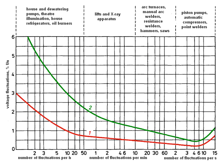
Voltage fluctuations, due to the effects caused by them, are characterized by two parameters: the amplitude of fluctuations and frequency of occurrence. The most harmful are fluctuations of 6-10 Hz. Fluctuations of this frequency cause flickering of light produced by light receivers, which can be sensed by human eyes. The sensitivity of the human eye to voltage fluctuations is shown in the diagram in Fig. 3.4.
Other devices sensitive to voltage fluctuations include: radios, televisions, precision measuring and control devices, computers and digital systems.
Voltage fall is a rapid reduction of the supply voltage to a value between 90% and 1% of the voltage before the voltage drop, after which the voltage returns to its previous value in a short period of time. The duration of the voltage drop is from 10 ms to 1 minute. The depth of the voltage drop is defined as the difference between the minimum effective voltage during the drop and the voltage before the drop. Changes in the supply voltage that do not cause it to drop below 90% of the voltage before the event occurs are not considered drops. Voltage drops are usually caused by short circuits in the network.
Asymmetry of voltages in the network
In power network calculations it is usually assumed that the series impedances of lines and transformers are symmetrical and also that load currents and supply voltages are symmetrical. This greatly simplifies the calculation process.
For more correct calculation of stationary network states, two types of asymmetry should be distinguished:
a) internal asymmetry of network elements (lines and transformers) caused by different self-impedances and mutual impedances in individual phases, for example in overhead lines,
b) external asymmetry:
– voltage asymmetry in supplying points,
– load asymmetry caused most often by the fact that loads connected at individual points of the network have different powers in individual phases. The most important in practice is the asymmetry in LV networks.
When the supply system is loaded by asymmetrical receivers, voltage drops and losses vary in different phases, so that the voltages at the terminals of the receivers are asymmetrical. These voltages differ in absolute phase voltages and the vectors are shifted by angles other than 120 degrees.
Non-symmetrical receivers which cause voltage asymmetry in the network are:
– sets of single phase receivers connected to a three-phase line, for instance induction furnaces, transformer welders, single phase traction,
– three phase receivers with non-symmetrical instantaneous load, for example arc furnaces during charge melting,
– non-uniformly arranged single phase receivers connected between phase conductors and neutral, met at utility customers fed from low voltage network.
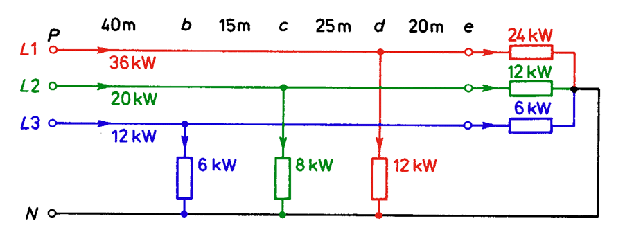
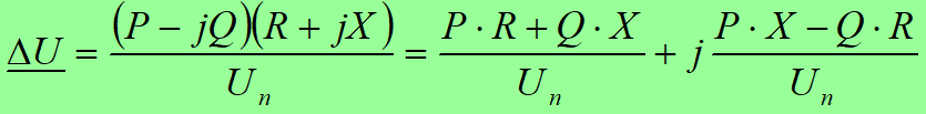
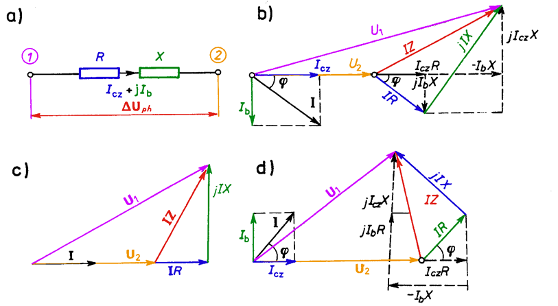
Voltage loss in a power network element (e.g. line segment, transformer, reactor) is the geometric difference of voltages at the beginning and at the end of the element (Fig. 3.6). In the case of a three-phase element voltage loss may be computed from the formula:
or from the formula:
The term “voltage drop” is used more frequently than voltage loss in electricity grid calculations. A voltage drop in a network element is the algebraic difference between voltages the beginning and the end of the element. In practical calculations it is usually assumed that the voltage drop is equal to the longitudinal component of voltage loss. An error made at this simplification is very small for small values of the angle. For the angle = 0 the error is equal to zero.
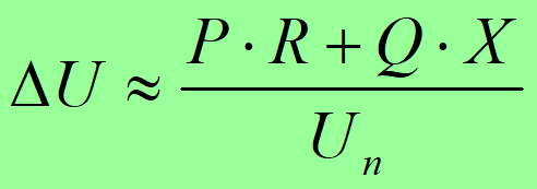
The approximate value of the voltage drop can be calculated from the formulae:
In three phase elements:
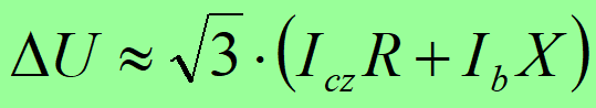
or
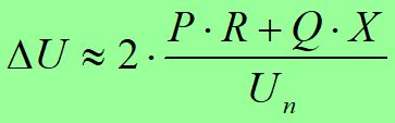
In a single phase line, in the case when the cross section of a single phase conductor is equal to the cross section of a neutral conductor:
[latex]\Delta U \approx 2 \cdot (I_{CZ}R – I_bX)[/latex]
or
The value of the voltage drop expressed in percents is often used:
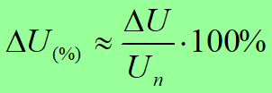
DEFORMATIONS OF CURRENTS AND VOLTAGES
One of the important indices of electric energy quality is the shape of the voltage curve. The distortion factor is a measure of the degree of deformation:

and in percents
![]() where: Usk,i – effective value of the i-th voltage harmonics.
where: Usk,i – effective value of the i-th voltage harmonics.
The main cause of voltage deformation existence is the flow of higher harmonics occurring in currents drawn by non-linear receivers. Those devices, converting a certain part of energy taken at network frequency of 50 Hz into energy at frequencies of higher harmonics, act as generators of current higher harmonics, i.e. they introduce higher harmonics of current to the supply network. The flow of current higher harmonics causes appearance of harmonic voltage drops in network elements impedance, which influence on basic sinusoid causing its deformation.
At present, the greatest influence on the degree of voltage deformation have rectifiers installed in the substations of railway and tramway traction.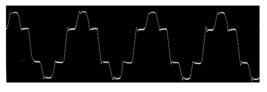 Oscillogram of a current flow in a thyristor rectifier substation feeding a tram network
Arc furnaces are also the sources of current higher harmonics. They are widely used in metallurgical industry (Fig. 3.8).
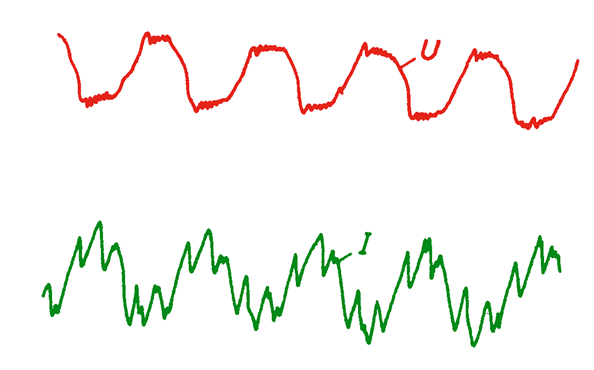 Fig. 3.8. Oscillogram of a current and voltage flow on electrodes of an arc furnace
Thyristor control systems of power intake, in lighting devices, heaters and electric engine control are active sources of higher harmonics.
From LV receivers radio sets and television sets have the highest percentage of higher harmonics in the current drawn from supplying network (Fig. 3.9).
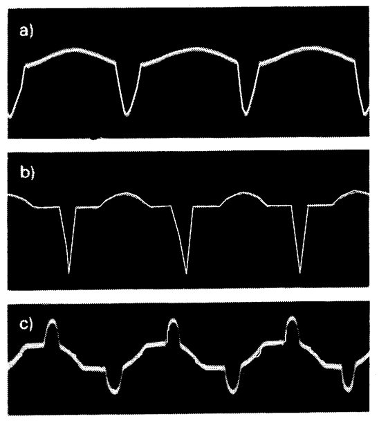 Fig. 3.9. Oscillograms of current flow of radio sets and tv sets: a) black and white tv, b) colour tv, c) radio set
Discharge lamps have important influence on voltage deformation in LV networks (Fig. 3.10).
From network devices batteries of capacitors installed in MV and LV networks have significant, usually negative, influence on the degree of voltage curve deformation.
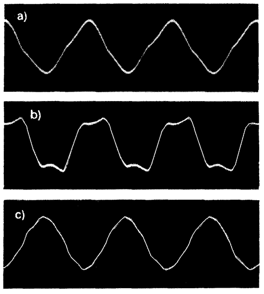 Fig. 3.10. Oscillograms of discharge currents in sources of light: a) single fluorescence tube, b) tubes in anti-stroboscopic system, c) mercury lamps
EFFECTS OF HIGHER HARMONICS
Higher harmonics have negative impact on the various components of electrical systems and receivers and on their operating conditions.
In electric machines (synchronous and asynchronous motors) powered by higher harmonics increase of power losses is observed, which results in increased heating and reduced efficiency coefficient. In air gaps and in the insulation of high voltage machines and other electric equipment (motors, transformers, cables, capacitors) higher harmonics cause increased partial discharge, resulting in an increase of the loss factor tg, and in consequence significant weakening of the insulation.
This creates the conditions for parallel resonance in the network, especially when the network has installed capacitor batteries. This resonance usually takes place for the fifth and seventh harmonics. It causes overvoltages, which can lead to damages of insulation, capacitors and cables. The resonance may also cause malfunctions of protecting equipment and protection devices.
The existence of harmonics in voltage curve and current curve limits transmission capability of power networks and decreases their efficiency.
The harmonics have particular influence on digital automation systems and computer system. They may cause their malfunction andmay even lead to their failure.
Higher harmonics cause malfunction of protection systems and automatic protection devices as well as false indications of measuring devices. They cause disturbances in communication systems.
An international standard IEC 61000-3-2:2018 limits mains voltage distortion by prescribing the maximum value for harmonic currents from the second harmonic up to and including the 40th harmonic current.
In Poland requirements concerning PQ of supply voltage limit THD level in the point of connection of a consumer to the network:
LV: THD ≤ 8%, each harmonic/U1 ≤ 5%
MV: THD ≤ 5%, each harmonic/U1 ≤ 3%
Methods of harmonics content limitation
The values of disturbances in the voltage are inversely proportional to short-circuit power in the feeding point of the network (bus-bars of a distribution transformer substation). Therefore, from the point of view of voltage deformation, short circuit power should not be reduced too much. Separation of medium voltage windings of a 110/MV transformer for feeding a customer with non-linear receivers practically ensures elimination of the influence of this customer on MV distribution network supplied from the second windings of this transformer.
At the same time, however, it increases the voltage deformation for customers connected to the same winding as non-linear receivers.
In the case of converters with a high power unit (over 1000 kW), the installation of a 12 pulse inverter system instead of a 6 pulse system has positive effects, since the fifth and seventh harmonics are significantly reduced.
Filters for individual harmonics are used for some high power customers. They usually contain reactor and capacitor connected in series.
A dumping resistor may be connected in parallel with the reactor (Fig. 3.11).
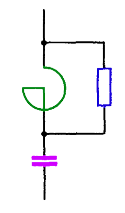
The filter is designed for a specified harmonic, with which it comes into series resonance and then it has very small impedance. It means short-circuit for the current of this harmonic, preventing its flow to the network. Wide-band harmonic filters are more and more commonly introduced, until now with not too high powers, based on thyristors.
Reliability of electric power devices
Devices can be divided into two main groups: reparable devices and unreparable devices.
In most cases electrical power devices are reparable, in which replacement of a defective component restores the ability to operate. In practice, when constructing a mathematical model of the operation process of repairable devices, a simplifying assumption is applied: the state of each device is described by a stationary random process,
– processes describing the element state are independent processes.
If the events consisting in formation and clearing of damages are discrete, single and independent, then according to the stochastic process theory the length of time of expectation for the damage and the duration of repair are values independent from the starting moment and number and time of formation of previous damages.
The values of these times are constant and equal to the average time of work between the damages

and value of average of repair duration
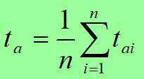
where tai duration of device repair after i-th damage, tdi – time of device operation between the damages (i – 1, i), n – number of cycles work-repair.
The reciprocal of the average time of work between the damages is called intensity of damages.
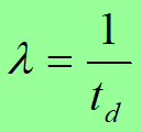
The intensity of damages may be also determined from the formula
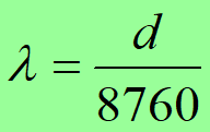
where d frequency of damages (number of damages during one year a = 8760h)
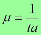
The reciprocal of average repair duration is called intensity of repair
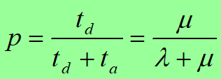
The ratio between real time of device work and required time of its work is called the coefficient of ability
and the ratio of repair duration to required time of work is called the coefficient of disability.
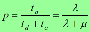
Because p + q = 1, these coefficients may be interpreted as probabilities that the device is in the state of ability or in the state of damage (in repair).
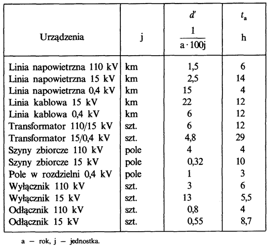
In practice, the coefficient of disability of a device is computed from the formula
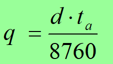
In the failure frequency statistics, the failure frequency is defined as the number of failures:
– per 100 km per year for lines,
– per 100 units for transformers, switches, etc.
Reliability indices of electric power devices
Own study:
Reliability of electric power systems – check what is the meaning of these two factors – indices:
SAIDI ?
SAIFI ?
System Average Interruption Duration Index
System Average Interruption Frequency Index
[latex][/latex]