
17 Matrices and equivalent schemes of transformers (fin)
The aim of the laboratory task is to carry out the equivalent circuit of a transformer. The presented calculations are commonly used in order to determine the resistance and reactance of the main and shunt branch of the transformer. Those data are necessary to analyze power system and compute e.g. power flow. The following manual shows methods of obtaining those parameters
Interpretation of equivalent circuit elements
Typical equivalent circuit is presented in figure 1.
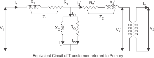
R1, R2‘ – resistance of the primary and secondary winding,
X1, X2‘ – reactance which is the representation of leakage flux of primary and secondary side,
RFe – resistance which is the representation of the core losses of active power – histeresis and eddy currents,
Xμ – reactance which is the representation of main flux in the core.

Idle state test
The idle state of the transformer we call the state in which one of the windings is supplied with nominal voltage from the source of electric energy, and the terminals of the second windings are opened. This test is used to calculate the parameters of the shunt branchof the equivalent circuit (Xμ, RFe ). To do that follow those equations:
ΔPFe ≅ P0,
IFe = P0/3V0,
Iμ = √(I02-IFe2),
Xμ ≅ V0/Iμ,
RFe ≅ V0/IFe,
Short-circuit state test
The short-circuit state of a transformer is a state in which one of its windings is fed from the source of electric energy, and the terminals of the second windings are shorted and rated current flows in them. In this conditions the voltage across the shorted windings terminals is equal to zero – in spite of that the current flows in it – it does not give any power outside the transformer. Total real power, taken by the shorted transformer covers only losses in windings, changing itself totally into heat.
ΔPCu ≅ Pz,
ZT = UZ/IU,
RT = PCuz/IU2 ≅ PZ/3IU2,
XT = √(ZT2-RT2),
Laboratory task
At idle test we expect high supplying voltages and small currents. Investigated transformer may be a four-windings transformer. That is why, testing a two-winding transformer we ought to:
- Supply voltage to terminals A2, B2, C2, which corresponds to feeding by phase voltage 220 V (middle taps of upper windings).
- We short terminals X, Y, Z creating, in this way, primary windings connected in star (Y).
- Because tested transformer may be four-windings transformer we short terminals Xs2 – As1, Ys2 – Bs1, Zs2 – Cs1 and terminals Xs1-Ys1-Zs1,in this way getting secondary transformer windings connected in star of phase-to-neutral voltage 127 V. We have transformer of connection group Yy0.
- The terminals of secondary winding As2, Bs2, Cs2 we left open (idle state).
- The terminals of the fourth winding are left open.
Now we set the ranges of voltmeters and wattmeters.
- The range of voltmeter we set at V, alternating current and 300 V (the conductors
should be connected to terminals „+”and „+”). - The range of ammeter (voltmeter) we set at V, alternating current and 1V (the
conductors should be connected to terminals „+”and „+”). It enables to measure
current in the range of 0 – 10 A. The current is measured with the help of voltage drop
measurement across resistor of resistance 0.1 ..Every 100 mV corresponds to 1A. - Wattmeter voltage coils we set at 400 V (because the voltage will be 220 V).
- Wattmeter current coils we set at 1A. We expect currents less than 1 A. Switch P of
wattmeters we set at position x1. - We calculate wattmeter constant remembering about wattmeter P multiplier.
Measurements
- We switch on circuit-breakers: WG (main), WZ (supply), WT (transformer) at supplying voltage equal zero.
- We delicately roughly increase voltages (every about 20V) in each phase to the level of about 220 V, observing them on meters VA, VB, VC, and then precisely with the help of voltmeter. Sudden increase of voltage to 220V successively in each phase would cause asymmetry and protection operation.
- We read the currents with the help of ammeter (voltmeter) and real powers with the help of wattmeters.
Short circuit test from the upper voltage site
We change the transformer connection.
- Supply voltage to terminals A2, B2, C2, which corresponds to feeding by phase voltage 220 V (middle taps of upper windings).
- We short terminals X, Y, Z creating, in this way, primary windings connected in star (Y).3. Because tested transformer may be four-windings transformer we short terminals Xs2 – As1, Ys2 – Bs1, Zs2 -Cs1 and terminals Xs1 – Ys1 -Zs1, in this way getting secondary transformer windings connected in star of phase-to-neutral voltage 127 V. We have transformer of connection group Yy0.
- The terminals of secondary winding As2, Bs2, Cs2 we short (short circuit state).
- The terminals of the fourth winding are left open.
Now we set the ranges of voltmeters and wattmeters.
We expect small supplying voltages and high currents.
- The range of voltmeter we set at V, alternating current and 30 V (the conductors should be connected to terminals „+”and „+”). The short circuit voltage value is about 10% of a transformer rated voltage (in this case rated voltage is 220V).
- The range of ammeter (voltmeter) we set at V, alternating current and 1V (the conductors should be connected to terminals „+”and „+”). It enables to measure current in the range of 0 – 10 A. The current is measured with the help of voltage drop measurement across resistor of resistance 0.1 ..Every 100 mV corresponds to 1A.
- Wattmeter voltage coils we set at 25 V (because the voltage will be low).
- Wattmeter current coils we set at 1A. We expect currents about 10 A. Switch P, multiplying coefficient of wattmeters, we set at position x10.
- We calculate wattmeter constant remembering about wattmeter P multiplier.
Measurements
- We switch on circuit-breakers: WG (main), WZ (supply), WT (transformer) at supplying voltage equal zero.
- We delicately roughly increase currents (every about 2 A) in each phase to the level of about 10 A, observing them on meters AA, AB, AC, and then precisely with the help of voltmeter (ammeter). Sudden increase of current to 10 A successively in each phase would cause asymmetry and protection operation.(It would be better to set them at
11.4 A, which is rated current, but we are limited by the table meters which have range to 10 amper only, but we can recalculate them later into rated conditions) - We read the currents with the help of ammeter (voltmeter) and real powers with the help of wattmeters.
- After measurements we decrease voltages to zero.