
2 Electric Generators
Sources and forms of energy
The following sources and forms of energy have been used for conversion on electric energy:
• primary fuels (organic: solid, liquid, gaseous and nuclear)
• energy of waters (inland and high tides and low tides of the seas),
• geothermic energy (heat from the interior of the earth),
• wind energy,
• solar energy,
• energy from chemical reactions.
Thermal power stations
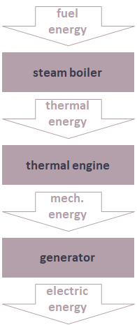
An enterprise generating electric energy on industrial scale and using for this purpose energy of organic (conventional) or nuclear fuels is called thermal power plant. The scheme of energy conversion in majority of thermal power plants takes place in three-steps.
Division of thermal power plants
According to the type of the thermal engine, thermal power plants are divided into:
• conventional steam power plants in which steam produced in a boiler is the working medium and it works in a steam turbine,
• steam nuclear power plants, in which process of fission of nuclear fuels in a reactor transfers thermal energy to the working medium,
• gas-turbine power stations in which gas, being the product of fuel burning, is the working medium and it works in a gas turbine,
• internal-combustion power stations with combustion piston engines (usually Diesel).
Conceptual diagrams
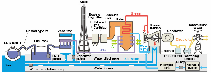
Condensing power plants steam as a main medium
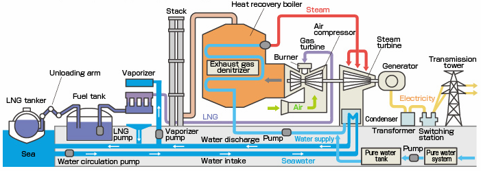
Condensing power plants gas as a main medium
Division of thermal power plants
Division of thermal power plants according to the type of energy output :
• condensing power plants – using only electric energy in condensing turbine-generators (they do not use the heat of exhaust steam),
• combined heat and power stations (CHP, cogeneration) – generating electric energy and thermal energy, which is given outside as steam or hot water, in the amount of at least 10% of produced energy. Electric and thermal energy are produced in a CHP simultaneously,
• combined cooling, heat and power (CCHP, trigeneration) – generation of electricity and useful heating and cooling from the combustion of a fuel.
The terms cogeneration and trigeneration used above may also be applied to the power systems generating simultaneously electricity, heat and chemicals – e.g. syngas or hydrogen.
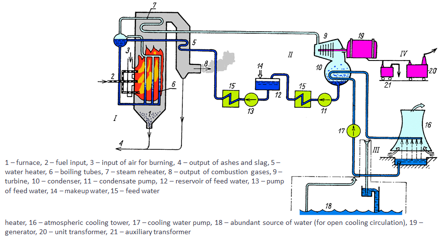
In technological process of thermal coal-fired power plant one can distinguish four important systems:
• fuel – air – combustion gases system,
• steam – water system,
which corresponds to main working medium circulation,
• cooling system of condensers,
• system of electric power output from power station.
I – fuel-air combustion gases system,
II – thermal system,
III – cooling system,
IV – system of power output
Steam nuclear power plants
• Three basic elements can be used as a fuel: uranium, plutonium and thorium.
• Isotopes Uranium-233, Uranium-235 and Plutonium-239 are the most commonly used.
• In fission reactors the fuel is usually based on the metal oxide because the oxide melting point is much higher than that of the metal. It is already in the oxidized state, so it also cannot burn.
• In the process of fission unstable nuclei are hit by a slow-moving neutron, they split, creating two daughter nuclei, two or three more neutrons and thermal energy. These neutrons then are hitting more nuclei. This creates a chain reaction.
• Released heat is used to generate steam that drives a steam turbine.
Scheme of a thermal-neutron reactor:
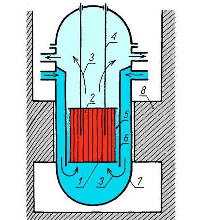
1 – fuel rods
2 – moderator
3 – coolant
4 – control rods
5 – neutron reflector
6 – thermal shield
7 – reactor’s reservoir
8 – concrete shield
Hydro power stations
Potential energy of water-courses is used in hydro power stations. These water races must be dammed up to make the difference between lower and upper reservoir. Water flows from upper to lower reservoir through water turbines.
The most important parameters of water power station are:
• installed power P,
• discharge flow of the power station Q
equal to the volume of water flowing through all the turbines of the power station during a unit of time, in m3/s,
• gross head
equal to the static difference of levels between upper and lower water,
• time of operation during 24 hours, week etc.
• efficiency.
In principle hydro power stations may be divided into:
Run-off-river power stations have no reservoir for water storage, they use continuous flow of water. Hydro power station in Włocławek is classical example of this type.
Pumped power stations – operate as power stations during load peaks and as pumping plants during off-peaks periods, pumping water from lower to upper reservoir.
Reservoir power stations have big water tanks which can store huge amount of water. They enable better readjustment of power plant to the needs of electric power system.
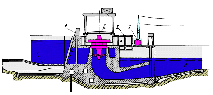 Cross-section of the hydro power plant in Włocławek:
1, 2 – consolidation of the bottom by concrete blocks; 3 – drain gallery; 4 – grid cleaner; 5 – mobile hoods above generators; 6 – road bridge; 7 –transformer station; 8 – room for the staff
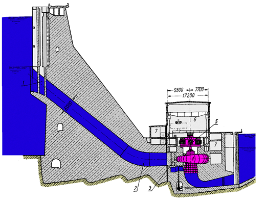 Reservoir power station with pumping unit in Solina
Depending on the head in hydro power stations the following types of turbines are used:
• At low and very low heads (3-80 cm) Kaplan turbines and pipe turbines, in which the turbine and generator in common enclosure are immersed in water.
• At medium heads (50-600 cm) Francis and Deriac turbines are applied.
• At high heads (300-2000 cm) Pelton turbines are used.
Hydrogenerators used in water power plants are synchronous generators with salient poles. Depending on the turbine type there are used generators with vertical or horizontal shaft with rotational speed 75-1000 r/min. Generator’s power is usually adjusted to turbine generating power. In case of reversible units, in pumped power stations, generator’s power is adjusted to the pumps’ power, because power needed for pumping is usually higher than power given by the turbine.
The largest hydro power plants in the world
| Rank | Name | Country | River | Years of completion | Installed capacity [MW] |
| 1 | Three Gorges Dam | China | Yangtze | 2008 | 22,5 |
| 2 | Itaipu Dam | Brazil / Paraguay | Paraná | 1984 | 14,0 |
| 3 | Xiluodu | China | Jinsha | 2014 | 13,9 |
| 4 | Guri | Venezuela | Caroní | 1978 | 10,2 |
| 5 | Tucuruí | Brazil | Tocantins | 1984 | 8,4 |
| 6 | Grand Coulee | United States | Columbia | 1942 | 6,8 |
| 7 | Xiangjiaba | China | Jinsha | 2014 | 6,4 |
| 8 | Longtan Dam | China | Hongshui | 2007 | 6,4 |
| 9 | Sayano–Shushenskaya | Russia | Yenisei | 1985 | 6,4 |
| 10 | Krasnoyarsk | Russia | Yenisei | 1967 | 6,0 |
Distributed generation
Dissipated (distributed) generation includes generating units with power, according to CIGRE (International Conference on Huge Transmission Networks), less than 50-100 MW, and according to EPRI (Electric Power Research Institute – USA) with power from a few kW to 50 MW. It contains the following types of units:
• RES – renewable energy sources
In particular it is energy of rivers, wind, biomass and energy of solar radiation in solar cells,
• CHP – cogeneration units,
• DG – units with modular construction.
Hydro power stations
Small hydro power plants, with installed power up to 5 MW and efficiency up to 90%, are very attractive for the environment.
Their particular advantage is fast start-up and possibility of nearly immediate loading. They use the potential of tiny rivers, agricultural retention reservoirs, irrigation systems, water supply systems, sewage systems and by-channels.
They can be built in 1-2 years. Their technical simplicity guarantees high reliability and long time of operation. They need few staff and may be remotely controlled.
Wind power plants
From renewable electric energy sources wind power plants gained the greatest success. Annual rise of over twenty percent of installed power was observed in wind power plants in recent years. From the technical point of view wind power plants are divided into:
• autonomic wind power plants with synchronous generators, working in separated network or cooperating with the network of power industry through thyristor/transistor converters,
• wind power plants with asynchronous generators cooperating with electric power network individually or in the farm system.
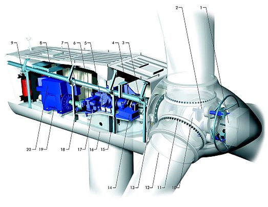
Structure of wind turbine V80 Vestas (2MW)
1. controller,
2. servo-motor of the device setting blades,
3. main shaft,
4. oil cooler,
5. gear box,
6. control system,
7. outage brake,
8. lift for the staff,
9. transformer,
10. blade spider,
11. blade bearing,
12. blade,
13. rotor braking system,
14. hydraulic system,
15. disk of rotor braking hydraulic system,
16. ring of directional system,
17. carrying frame,
18. gear of directional system,
19. generator,
20. generator cooler
Basic advantage of wind power stations is that they generate electric energy using inexhaustible energy source and they do not send harmful substances to natural environment.
Basic disadvantages of wind power plants are:
• emission of noise during operation,
• they cause electromagnetic disturbances,
• they need large areas,
• they deform the landscape,
• they kill birds and bats in the radius of several km,
• they work only at suitable speeds of the wind.
Key facts:
• Total capacity of wind turbines installed worldwide reached over 514 GW by the end of 2017 . More than 47 GW were added in the year 2017.
• Installed wind turbines can cover more than 5% of the global electricity demand.
• Globally the highest power installed in wind power plants is in China 188 GW, and highest share is in Denmark with 43% of its power coming from wind (5,3 GW).
• The highest power installed in wind power plants in Europe is now in Germany – it is over 56 GW. There is about 6500 MW installed now in Poland.
Photovoltaic system
Photovoltaic cells are commonly used in countries with high insolation. They are formed of semi-conductive material, which under influence of solar radiation absorption generates direct electric current, taking advantage of photovoltaic effect.
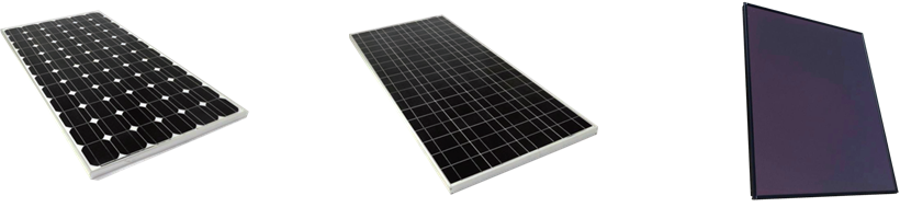
 Monocrystalline panels – oldest type of PV panels
• Typical single cell has an area of about 100 cm2 and at full light generates power of about 1.5 W at the voltage of 0.5 V.
• Voltage remains quasi constant, independently from light intensity, and current is directly proportional to the intensity of solar radiation.
• To receive higher voltages and currents, the cells are connected in series and in parallel in so called photovoltaic modules of power from <50 W to ~300 W.
• Currently monocrystalline panels are the most efficient (typically ~20%) type of PV panels.
• Single cells are made through the Czochralski method where a silicon crystal ‘seed’ is placed in a vat of molten silicon. Then seed is slowly drawn up with the molten silicon forming a solid crystal structure around the seed known as an ingot which is later sliced to a silicon wafers. This is then made into a cell.
Policrystalline (Multicrystalline) panels
• Polycrystalline cells are slightly less efficient than Monocrystalline (typically 14-16%, last developments up to 21% )
• They have become the dominant technology on the residential solar panels market because of the cheaper method of production.
• Polycrystalline “cell” also start as a silicon crystal ‘seed’ placed in a vat of molten silicon that is allowed to cool, which forms the distinctive edges and grains in the solar cell.
Thin film panels
• Thin film panels are a totally different technology – a photovoltaic substance is deposed onto a solid surface like glass.
• Commercially used photovoltaic substances used are: Amorphous Silicon, Cadmium Telluride (CdTe), Copper indium gallium selenide (CGIS), Dye-sensitized solar cell (DSC).
• They have the lowest efficiency (7-13%). However, with lowest material costs for thin film they are quickly becoming the more economically efficient.
Biomass power stations
Biomass power stations are becoming more and more common. Electric energy generation from biomass may take place through its direct burning in power stations or CHP’s or by burning biogas, oil or alcohol produced from biomass.
Biomass fuels come from:
• wood cuttings in forests,
• waste wood from sawmills, furniture factories and others,
• plants (i.e. straw) grown with the specific purpose of becoming biomass fuel.
Biogas is derived from organic matter digested by microorganisms in a process that produces gas as a result (mixture of 65% methane (CH4) and of 35% CO2).
The anaerobic digestion process occurs naturally with waste at landfills.
Carbon dioxide CO2 is a by-product of biomass combustion. But in this case it is neutral for natural environment, because through photosynthesis it circulates in closed cycle. There are no sulphur compounds in the combustion gases. However, the biomass may be polluted by pesticides and plastics waste, and in that case dioxins and furans, having toxic properties, may be send to the atmosphere.
Geothermal power stations
Geothermal power stations belong to the renewable energy sources. Depending on water temperature and the content of gases and salt, the following solutions are possible:
• high-temperature – steam from the deposit drives turbines directly,
• low-temperature – steam heats low-boiling medium which drives a turbine,
• high-pressure with methane – burned methane and water drive a 3-stage turbine in three cycles with lowering pressure and temperature.
Basic types of geothermal power plants:
• Dry steam plants – steam comes directly from a geothermal reservoir to turn generator turbines.
• Flash steam plants – high-pressure hot water comes from deep inside the earth and converts to steam to drive generator turbines. Cooled, condensed steam is injected back into the ground to be used again. This is most common type of geothermal power plant.
• Binary cycle power plants – heat is transferred from geothermal hot water to steam heater by another liquid.
Reciprocating engines
Reciprocating engines (also known as piston engines) are spark-ignition or diesel units with powers from 30 kW to 10 MW. They are running on the combustion of petrol, diesel, Liquefied petroleum gas (LPG) or compressed natural gas (CNG).
These generators are useful in small electric power systems because of:
• low powers,
• modular structure,
• low capital costs and
• short time of construction.
They are characterized by fast start-up, high reliability, they can follow characteristic of the receiver and they can recover heat.
These generators can serve as reserve-, peak-generators. They can be cogeneration- and working-on-separated-network units.
Gas miniturbines and microturbines
Gas miniturbines and microturbines are high reliability and availability generators, powered by natural gas, oil or working in bi-fuel system with powers from 30 kW to 5 MW.
They are characterized by:
• high efficiency (especially at cogeneration),
• low levels of emitted atmospheric polluters,
• light construction,
• low investment costs,
• fast start-up,
• high flexibility,
• possibility of remote control.
They may work as CHP units.
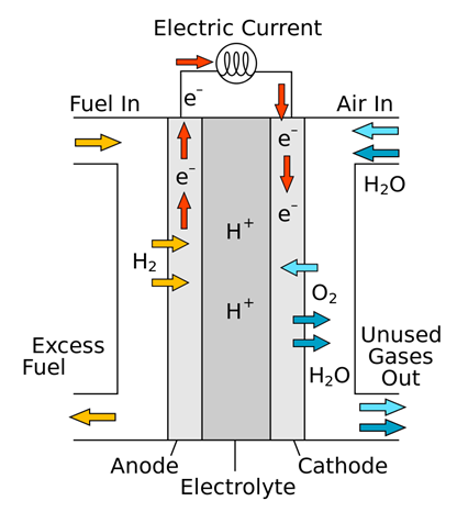
Fuel cells
Fuel cell is an electrochemical converter of fuel chemical energy (hydrogen, natural gas) directly into electric energy with efficiency up to 50%.
The fuel is supplied in a continuous way to the anode, while an oxidizer (pure oxygen or air) is also given in a continuous way to the cathode.
Electrolyte allows positively charged hydrogen ions (protons) to move between the two sides of the fuel cell.
Fuel cells can produce electricity continuously for as long as fuel and oxygen are supplied.
Fuel cell efficiency is typically between 40–60% and up to 85% in a cogeneration scheme.
Advantages of fuel cells:
• minimum amount of pollutions,
• simple adjustment to the changing energy demand,
• easy installation and fully automatic work,
• possibility of usage in cogeneration systems and low exploitation costs.
Fuel cells are divided according to the electrolyte membrane used in them:
• PAFC ( Phosphoric Acid Fuel Cell ) – temperature of work 200 C,
• MCFC ( Molten Carbonate Fuel Cell ) – temperature of work 650 C,
• SOFC ( Solid Oxide Fuel Cell) – temperature of work 1000 C,
• PEMFC (Proton Exchange Membrane Fuel Cell) – polymer, temperature of work 800 C.