
14 Operation of a synchronous generator in an electric power system and short-circuit currents (fin)
The goal of this laboratory training is getting knowledge about short-circuit current waveform in various circumstances
Basic information
Short-circuit – unintentional connection of two or more points of electric power system (EPS) directly or through an electric arc or an object of low impedance (earth is also treated as a point ofthe EPS). Short-circuits may be classified as follows:
- single or multiple faults,
- symmetrical (3 ph) or unsymmetrical (Zph-n, Zph, lph-n) faults,
- simultaneous and non-simultaneous faults,
- internal or external faults.
Some of the external causes for the short-circuits in EPS are:
- atmospheric discharge,
- insulation moistness,
- mechanical damage of line or cable (e.g. damage of poles, rime which could down overhead line, damaging the cables),
- dielectric breakdown caused by polluted insulators.
The internal causes for the short-circuit are:
- switching overvoltages,
- switching mistakes,
- long overloads of elements.
The results of the short-circuit are:
- heating elements by fault current,
- rise of dynamic forces between elements located close to each other,
- possibility of circuit-breaker explosion,
- deterioration of steel-concrete foundations of poles of MV by earth faults.
Short-circuit current waveform in EPS
As it was mentioned before the short-cirtuit is the connection of two point in the circuit with different potentials. Typically EPS elements (lines, transformers and generators) has two main parameters: R – resistance and X – inpednace, where X = jωL. The calculaction of RL type circuits leads to such results:
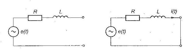
Fault current can be determined in the equation:
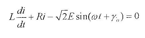
After solving differential equation i(t) has presented form:
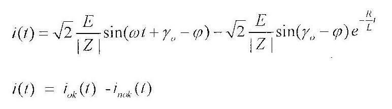 ,
,
where
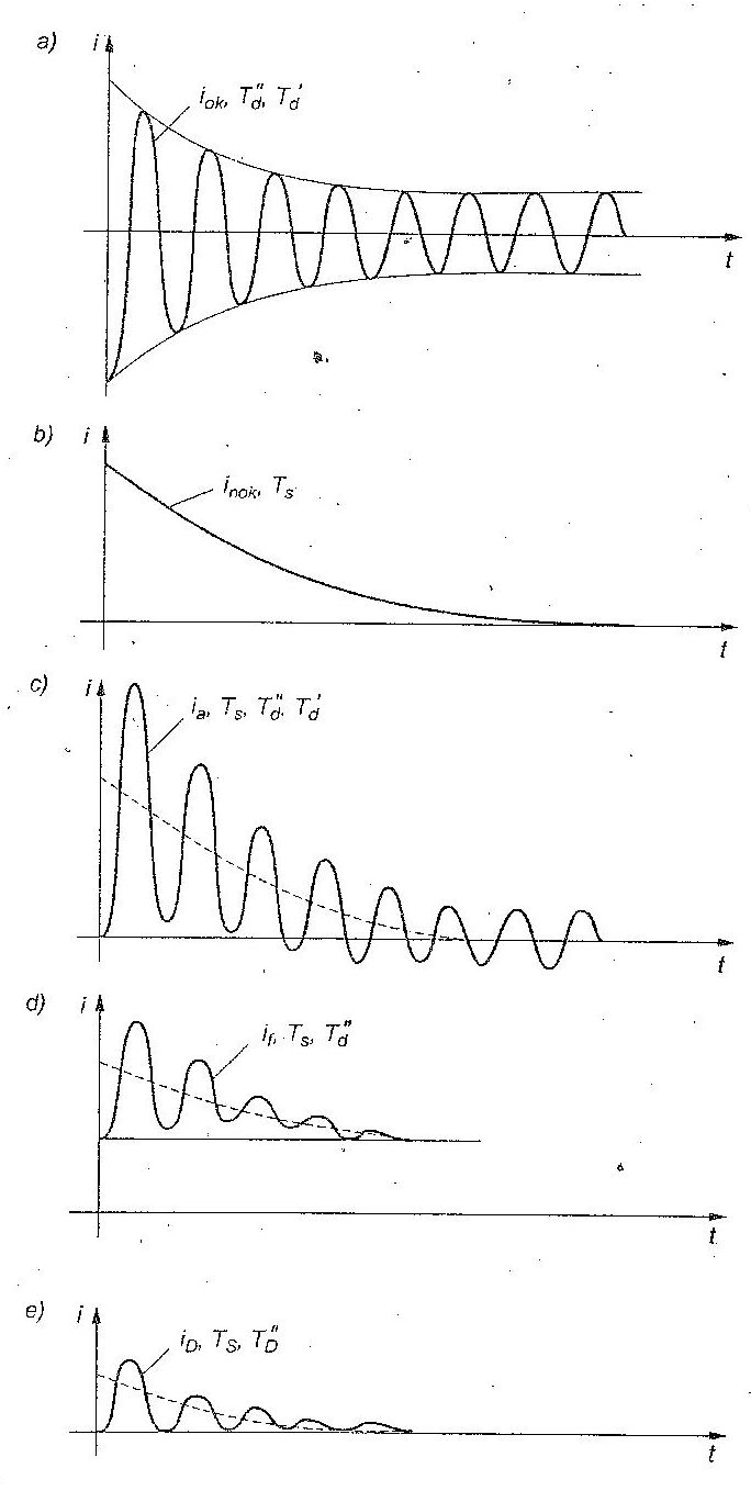
As it is easy to see i(t) has two components iok – AC component and inok – DC component. The graphical interpretation is presented in fig 2.
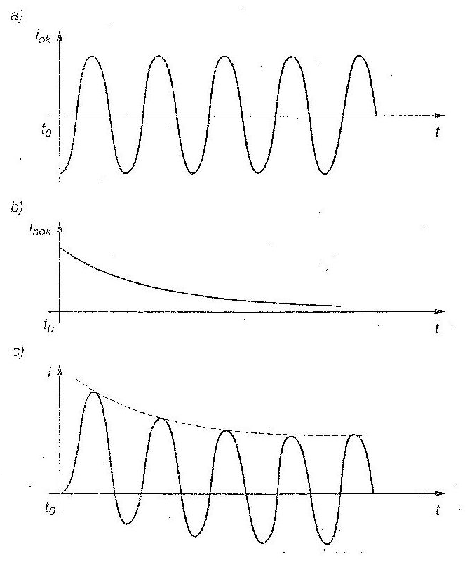
The presented waveform of fault current is valid to the sources with inner R and X is not changing its value during short-circuit.
Shorting of a synchronous generator
Figure 3 presents a synchronous generator in normal state of opertion. As you may see, the
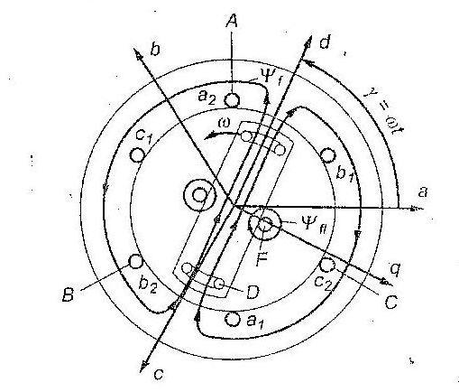
The synchronous generator, while short-circuit, has variable reactance. The reason for this is the fact, that the flux (Ψf – rotor flux) cannot change its value instantly. We may then distinguish three state of synchronous generator during fault:
- subtransient state,
- trasient state,
- continous state.
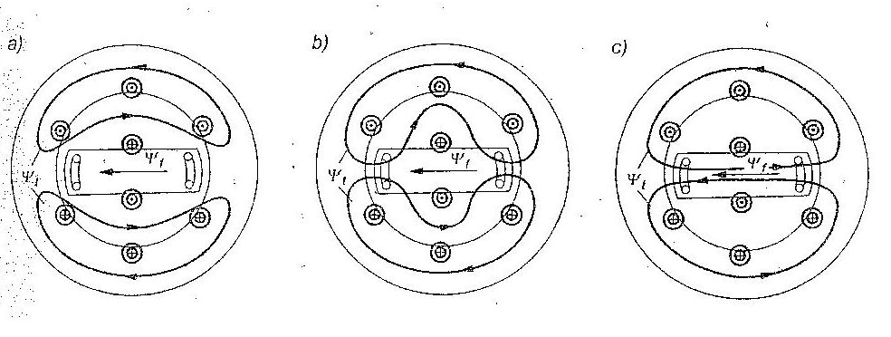
When the flux passes by the rotor, it is subtransient state. Resistance of rotor windings causes that currents created in them decay under the change of winding magnetic energy into heat. Resistance of dumping windings is high and the current decays very quickly. So in a short time after fault formation the stator flux coming from fault current can come in the part of rotor, what is illustrated in Fig. 4.b. The state of generator, in which stator flux comes in the part of rotor but is still pushed out beside field winding, is called the trasient state. The decay of current in the field winding is quite slow (low resistance). This current, decays after some time and the stator flux can go through the whole rotor without any obsticales. It is presented in Fig. 4c. This state is called steady state of fault.
Subtrasient reactance – Xd” = 18%, trasient reactance – Xd‘ = 36%, stady state- Xd =180% in relation to Z = U2n/Sn
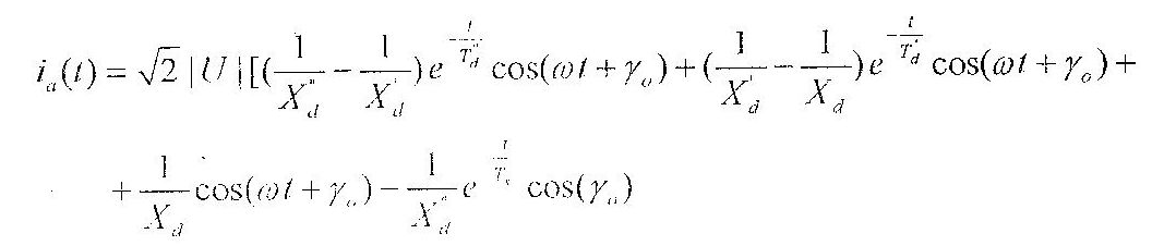
The final waveform of the short circuit current is shown in equasion below.
Laboratory describtion
Frontal panel of the laboratory stand is shown in Fig. 6. The system consists of the model of generator-turbine unit, synchronising column, model of the unit transformer, transmission lines, model of unit auxiliary transformer, transformer supplying distribution network with possibility of connection of static and dynamic load. Additionally there is also thyristor fault switch and measuring system.
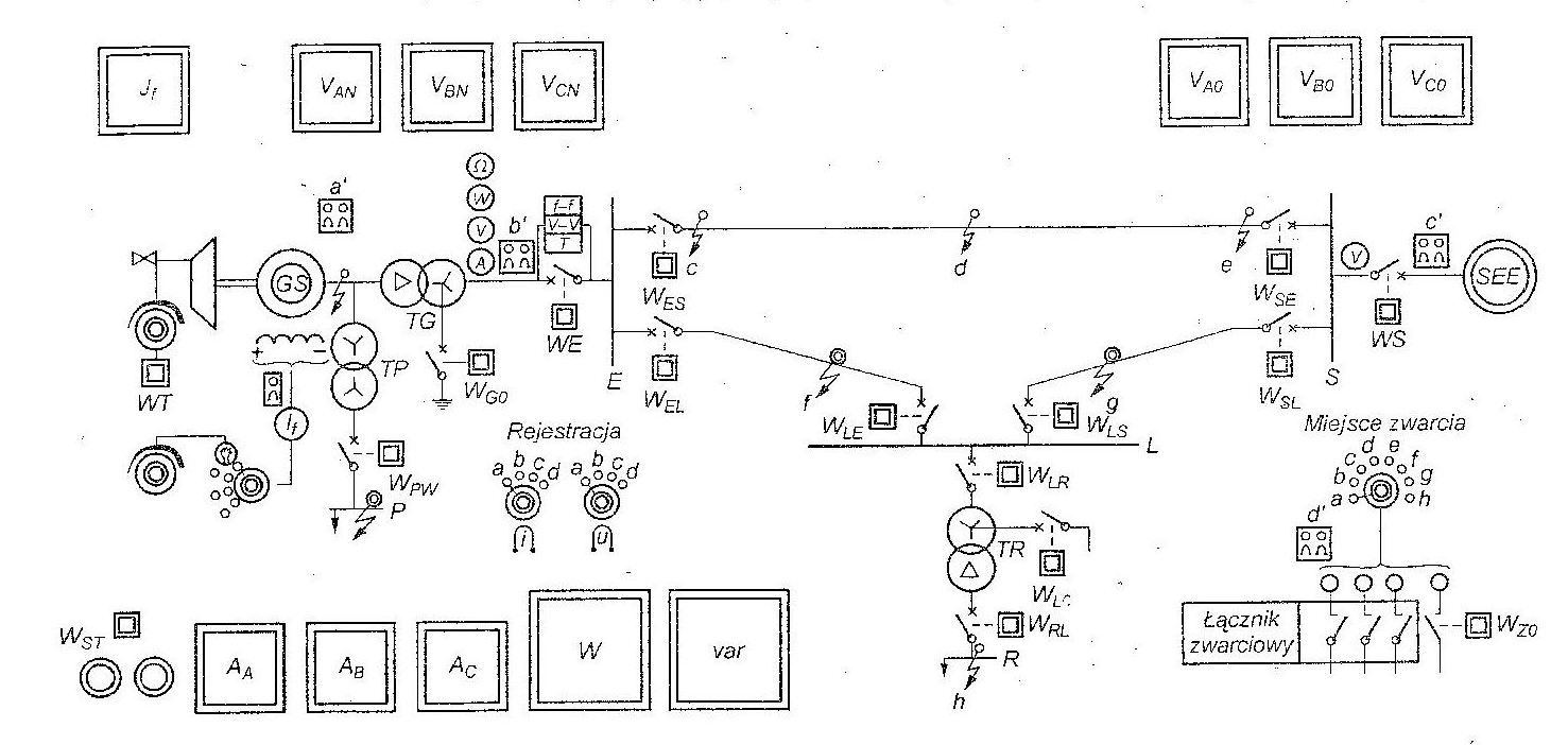
Frontal panel of the laboratory stand is shown in Fig. 4.6. The system consists of the model of generator-turbine unit, synchronising column, model of the unit transformer, transmission lines, model of unit auxiliary transformer, transformer supplying distribution network with possibility of connection of static and dynamic load. Additionally there is also thyristor fault switch and measuring system.
Program of investigations when the arrangement is connected to the system
1. Chose the variant of network configuration (in this case generator does not work) and by switch WS connect the chosen arrangement with the system.
2. According to point 4.4 perform a three-phase fault in successive accessible nodes and observe curves of short-circuit currents and voltages. Knowing the values of equivalent impedance of short-circuit loop, estimate the value of fault current in each point of fault and compare it with effective value of periodic component of initial fault current, read from the diagram .on the oscilloscope.
3. Investigate the influence of the angle of fault formation on the value of aperiodic component and estimate its time constant. Perform with the help of the recorder recording of the chosen extreme case, comment the oscillogram, present conclusions and attach oscillogram to the report.
Program of investigations in the network fed by generator model
1. According to point 4.4 synchronise the generator and connect it to the system network. Pay attention to transient state during synchronisation.
2. Switch-off the arrangement from the system network and perform three-phase faults successively in two chosen nodes. Observe curves of fault currents and voltages during the fault on oscilloscope. Pay particular attention on decaying of subtransient and transient components of periodic fault current and aperiodic component of fault current. Record extreme case of short-circuit. Present conclusions.
Program of investigations in the arrangement coupled with the system network
1. According to point 4.4 synchronise the generator and connect it to the system network. Set the generator power equal to 1 kW.
2. Perform a three-phase fault in a chosen point. Observe curves of fault currents and voltages during the fault on oscilloscope. Observe particularly how the fault current is distributed into sources. Record extreme case of short-circuit. Present conclusions.