
18 Voltage Regulation in Electric Power System (fin)
Voltage is one the basic electric energy quality parameter. The level of voltage has the influence on the proper functioning of the EPS. Lowered voltage in power system results in:
- higher power losses in transmission lines,
- limitation of the maximum power transfer in transmission lines,
- voltage stability threat,
- electric motor stalling.
The state of too high voltage can cause insulators failures and faults as a consequence.
The purpose of the laboratory task is the investigation of means of maintaining voltage at permissible level. During the laboratory classes students are going to observed different methods of voltage regulation and compare them between each other.
Voltage drop in transmission system
The control of voltage drop in transmission system is the key to maintain the voltage at permissible level. The typical situation is presented in phase vector in fig. 14.1.
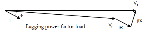
Vs = VR + ZI,
where Vs is voltage in the souce node, VR is the voltage in receivers node, Z is line impedance, I is current sent to the receiver.
I = S*/VR* = (P-jQ)/VR;
Vs = VR + Z(P-jQ)/VR = VR + (R+jX)(P-jQ)/VR = VR + (RP+XQ)/VR + j(XP-RQ)/VR
Typically j(XP-RQ)/VR can be neglected, so equation is simplified to this form:
VS = VR + (RP+XQ)/VR
In transmission grids resistance (R) of the line is smaller then inductive reactance (X), so to simplified voltage drop depends on reactive power consumption.
Methods of voltage regulation
To control the voltage in electric power system consists of:
- Synchronous generators excitation current control. By changing the generator excitation current the voltage regulator ensures maintaining the set value of the voltage at the terminals. Generator excitation control is the basic method of voltage regulation in the power system.
- Transformer tap changer – changing the transformer ratio by changing the active number of turns in one of the transformer’s windings. This regulation does not change the reactive power balance in the system, but, by changing the voltage levels in individual network nodes, it affects the change of power flow.
- A change in the reactive power flow in the power grid results in a change in the voltage drop in the grid, thus changing the voltage values in its nodes. Reactive power control is made using synchronous generators as well as additional sources of reactive power, e.g.a) batteries of parallel capacitors in distribution networks,
b) power electronic devices, such as SVC , or STATCOM (transmission and distribution networks).Static compensators are systems containing capacitors and / or thyristor controlled reactors. They are connected to the power grid nodes in parallel to the loads, so they constitute an adjustable susceptance, the value of which changes smoothly within the limits of capacitors and chokes. Due to the ability to quickly (follow-up) change in reactive power, these circuits are used in the case of the need to compensate for rapid voltage changes. - Changing the network impedance
The change of the network impedance influences the change of voltage drops and thus changes the voltage in the nodes of this network.
There are two ways to regulate voltage in network nodes:a) by changing the network configuration,
b) by using serial capacitors.Adjustment by changing the network configuration consists in switching on parallel elements, eg lines or transformers, under heavy load and switching them off when the load is low. The main purpose of changing the network configuration is to adapt the nominal power of the elements to the current load, and consequently, in addition to the voltage change, reduce the total active power losses in the network.
Transformers can operate in parallel connection, but must meet several conditions:
– transformer ratio equality (± 0.5%),
– same connection groups,
– equal short-circuit voltage (± 10%),
– rated power ratio not greater than 3: 1.
Laboratory stand
Fig. 14.2 presents the front panel of the laboratory stand.
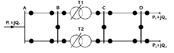
The physical model of a transmission system (three phase) has been realized on the stand. It consists of a series of the following eleinents. connected in chain:
- electric power substation A of Un = 220 kV with supply and a feeder bay of a double circuit line A-B,
- double circuit line A-B running to substation B,
- transformer electric power substation BC with busbars B of Un = 220 kV and with busbars C of Un = 110 kV with two transforiners operating in parallel. equipped with the voltage regulator of the type ABB SPAU 341C (one transformer) and manual ratio switch (second transformer),
- double circuit line C -D running to substation D,
- electric power substation D of Un = 110 kV with two complex, adjustable power loads P and Q,
- reactive power compensator with three sections user can manually set (1/3 QMAX, 2/3 QMAX, 3/3 QMAX).
In substations B, C and D there are sectionalised busbars.
It is possible to set the supply voltage in the substation A in the range of ± 15 %.
Each busbar system is equipped with voltage meter (indications in percent of rated voltage).
Tasks to do during the laboratory
- Investigation of voltage in node D (receiving node), as a function of PD and QD.
- Determination of voltage distribution along the line segment AB and CD in the idle and high loading state of operation.
- Investigation of the influence of reactive power compensation (all sections) on the voltage distribution.
- Investigation of the transformer tap changer as a way to regulate the voltage in the receiving node.