
5 Lines and substations
LINES AND SUBSTATIONS
This lecture is focused on the following types of electric power lines:
– overhead lines with bare conductors,
– overhead lines with insulated conductors,
– cable lines.
Different types electric power substations connected to these lines are also described.
An electric power line is a set of sufficiently insulated conductors used to transmit an electric energy.
An electric power substation is situated in one place set of electric power devices (together with necessary buildings) used for conversion, transformation and/or distribution of electric energy.
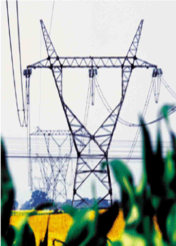
An overhead line with bare conductors it is an overhead device used for electric energy transmission, composed of not insulated conductors, insulators, supporting structures and fittings.
Lines of this type constitute majority of existing electric power lines.
Rated voltage of a power line it is the effective value of a phase-to-phase voltage for which the line is built.
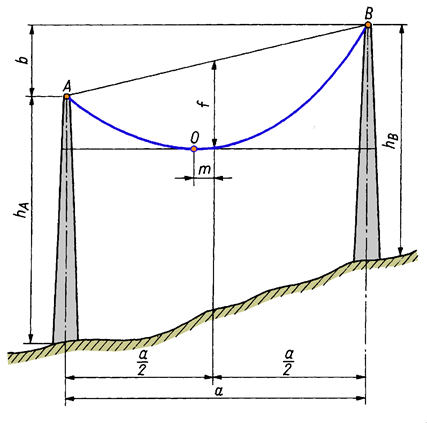
A part of an overhead line existing between neighbouring constructions
constitutes a span.
CONDUCTORS
Conductors are made of materials with the following features: high conductivity, atmospheric and chemical resistance and high mechanical strength. These are aluminum and its alloys, copper and tinned steel.
Conductors may be made in the form of wires and strands. Wires (denotation D) in LV lines are usually made of copper of cross sections: 4, 6 and 10mm2.
Commonly used are stranded (composed of 7, 19, 37 or 61 wires) with cross sections:
16, 25, 35, 50, 70, 95, 120, 150, 185, 240, 300, 350, 525 mm2.
Most commonly used types are:
- aluminum strands – AL (cross sections <70mm2; used in LV lines)
- steel – aluminium – AFL (used in MV and HV lines)
- aluminium alloys (used in selected coutries eg in France (Almelec alloy) are not used in Poland)
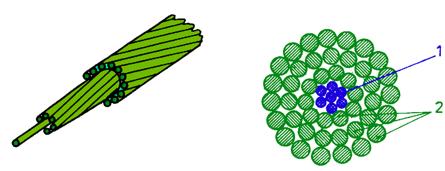
Bundle conductors are used in HV lines from 400 kV to reduce the intensity of electric field around the conductor and, at the same time, to limit the corona phenomenon i.e. electric discharges in a configuration: conductor – pole construction.
In old HV and EHV lines steel lightning conductors were used. O/FL had cross sections 50, 70 or 90 mm2 were made of steel wires which protect lines against atmospheric discharges. In modern solutions lightning conductors with light cables are used.
SUPPORTING STRUCTURES
Conductors of overhead lines are suspended on supporting structures – poles, dug in the ground directly or indirectly with the help of a foundation. Depending on the function, we distinguish between the following types of poles:
– through towers supporting the conductors, without taking over tension force of the conductor,
– anchor towers used for taking over the tension, installed every two to three kilomentres,
– angle poles situated on the bands of the line route,
– terminal poles at the ends of the line,
– tee-off poles (R) standing at furcation (branching) points.
Steel-reinforced contcrete poles are either vibraconcrete or pre-tensioned concrete.
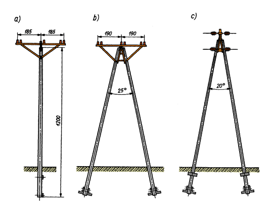
Steel poles are produced as lattice poles, installed at the site from prepared elements connected with pipe unions (Fig. 4.6) or as full walls made of tubes.
Prefabricated or on-site concrete foundations are used are used for foundation of steel poles.

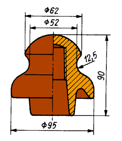
INSULATORS
Main task of insulators is insulation of power line conductors from each other and from supporting structures. Moreover insulators must stand conductor tension force and conductor weight together with rime (ice on the conductor).
They must be non-absorbable, weather resistant and chemical resistant.
They are made of porcelain or hardened glass.
Line insulators are made as:
stand (LV and MV lines) (Fig 4.7)
or
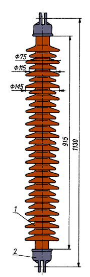
suspension (HV and EHV lines):
– cap-and-pin insulators (Fig.4.8)
– rod insulators (Fig.4.9).
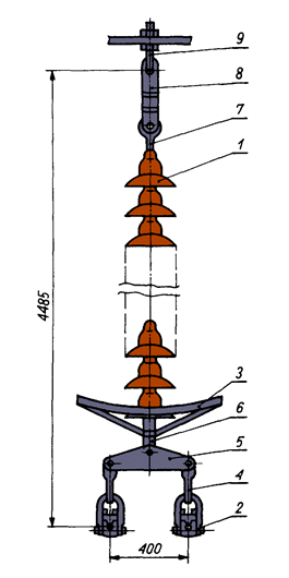
Suspension and connection of conductors
The way of suspension depends on that if the stand insulator or the chain of suspension insulators must stand the tension force. Suspension attachment (Fig.4.10) enables, when conductor is broken, its release from the coupling in case when the tension force does not exist (is not applied).
Tension attachment (Fig. 4.11) gets the tension of the conductors from both sides of the pole and must stand at least 80% of the force, that breaks the conductor.
Conductors are connected through connectors, terminals and couplings (Fig. 4.12), fulfilling certain electric and mechanical requirements.
GUIDING OF OVERHEAD LINES
• LV lines are usually routed along the streets.
• MV, HV and EHV lines are routed in such a way as to enable the most favourable connection of 2 stations.
The following principles are in force:
– the line should be as short as possible, without frequent and sharp bands,
– crossings with objects like: power and telecommunication lines, roads, railways and rivers should be avoided; crossing spans must fulfill special requirements (restrictions) according to the standards,
– densely populated areas should be avoided,
– flat terrains should be chosen,
– possibility of future network development should be taken into account,
– guiding through forests should be avoided, because this requires cutting of the surrounding trees in the belt along the line.
Overhead lines with INSULATED CONDUCTORS
Overhead LV and MV electric power lines with insulated conductors are insulated by a layer of solid insulation material – usually cross-linked polyethylene.
These lines contain two groups of elements fitted to each other: overhead conductors insulated by a thin layer of solid insulation, made of cross-linked polyethylene and specialized network equipment.
LV overhead lines with insulated conductors
The common feature in the solutions used in LV lines is that, that they do not need any additional insulators, and working conductors are industrially stranded in bundles. They differentiate in the way of fastening and carrying tensions.
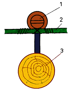
In Finn system AMKA and French system catenary (carrying) wire exists, which acts as neutral conductor (Fig. 4.13).
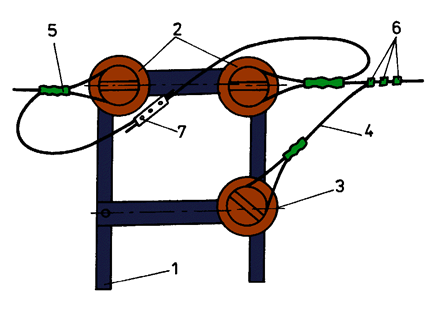
Self carrying system is commonly used in Poland and it does not need the carrying strand. Mechanic tensions are carried by four identical insulated working conductors (3 phase conductors and 1 neutral conductor) – Fig.4.14.
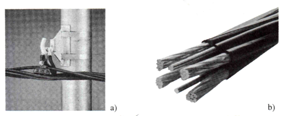
Fig. 4.13. Bundle of LV conductors in modified Finn system AMKA
a) suspension attachment,
b) construction of a bundle of conductors
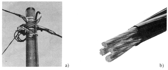
Fig. 4.14. Bundle of LV conductors in four-conductor system
a) tension attachment,
b) construction of a bundle of conductors
Phase conductors and neutral conductor, made of aluminium alloy of increased strength, have the same cross section in the four conductor system, in the range from 16mm2 to 120mm2.
Cross sections of illumination conductors (with two wires) have 25mm2 or 35mm2. Each of the conductors is insulated by a layer of cross-linking polyethylene of high density, resistant to majority of weather conditions.
In the four conductor system all the phase conductors and neutral conductor are held directly by tension clamps and suspension clamps ( Fig. 4.15).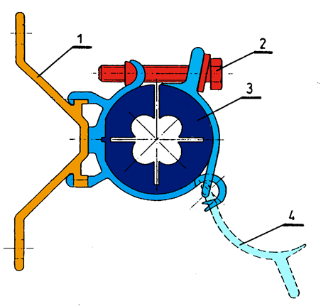
Fig. 4.15. Suspension clamp used for fixing on facades
1 – clamp body,
2 – set screw,
3 – gum insert,
4 – mobile part of the clamp
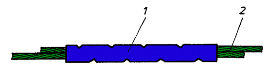
Particularly important elements of every insulated line construction are waterproof current terminals, piercing insulation (Fig. 4.16). They are used for branches and connections.
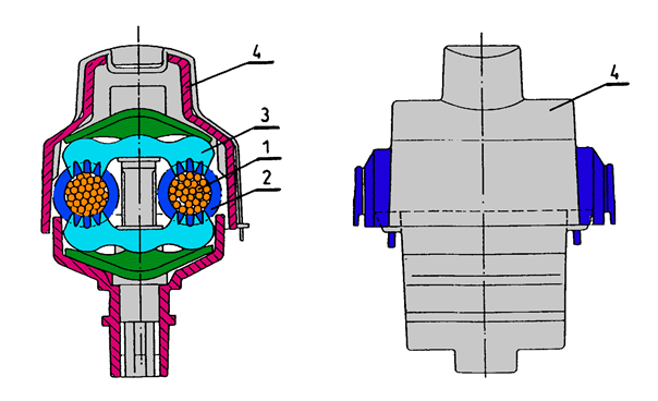
Fig. 4.16. Current terminal piercing insulation
1 – conductor core,
2 – insulation,
3 – upper facing with teeth piercing insulation,
4 – plastic housing
MV overhead lines with insulated conductors
There are three basic construction solutions of MV overhead lines with insulated conductors:
SAXKA system, in which conductors have full electric insulation, in the form of sufficiently thick layer of cross-linked polyethylene. The entire bundle is driven, industrially stranded with suitable catenary wire, with the help of which the bundle is directly suspended to supporting structures, without the usage of insulators,
ACS – AXUS system with conductors of incomplete insulation, fixed to the supporting structures by small support insulators (Fig. 4.17). The important feature of this system is self-supporting of the industrially stranded bundle of the phase conductor,
PAS system, used in Poland, is the simplest and the cheapest solution of MV insulated lines. Phase conductors, in this system, are guided separately (Fig. 4.18).
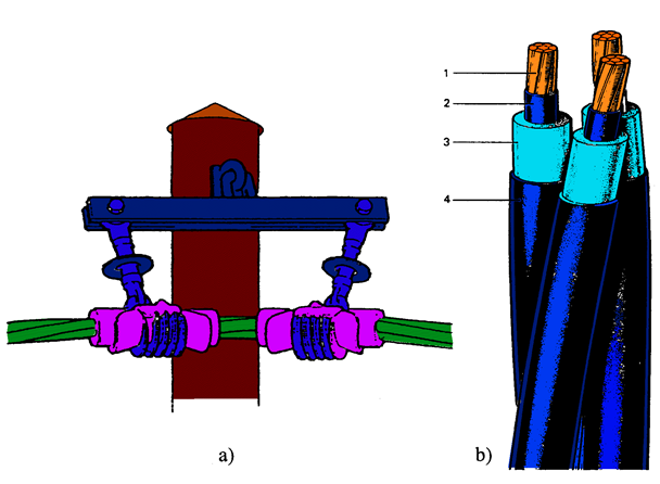 Fig. 4.17. MV overhead line
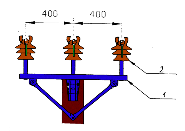
Fig.4.18. View of the top of a through tower of a MV line in the PAS system with conductors laid horizontally
Advantages of lines with insulated conductors
The most important advantages of insulated conductor lines are:
– high reliability, thanks to elimination of bare conductors,
– elimination of many troublesome exploitation measures, for example cutting of tree’s branches,
– reduction of safety distances to trees, buildings and other overhead lines – in case of LV lines to zero and significantdistance limitation in the MV PAS system,
– possibility of routing LV and MV lines on the same poles,
– high safety of the staff, outsiders and birds,
– reduction of voltage drops in relation with traditional lines, thanks to diminution of per-unit reactance,
The most important advantages of insulated conductor lines are:
– significant reduction of the risk of fire caused by short-circuit or breaking of a conductor,
– possibility of temporary exploitation of LV network even in case of overturning of a pole and dropping of conductors to the earth,
– possibility of further exploitation of a MV line, in the PAS system, together with trees lying on it even for longer period of time, which enables to undertake exploitation measures in convenient time,
– possibility of making exploitation measures in LV lines switched on,
– increased safety of people and animals,
– safe and simple connections in LV lines.
Disadvantages of lines with insulated conductors
The most important disadvantage of insulated conductor lines is higher investment cost in comparison with traditional overhead lines with bare conductors.
CABLE LINES
Types of cable lines:
• multi-conductor cable,
• bundle of single-core cables in multi-phase system,
• few cables single- or multi-conductor connected in parallel, together with fittings, laid on a common route and joining terminals of the same two single- or multi-phase or single- or multi-poles electric devices.
They are mostly used in industrial enterprises and in urban terrain, where guiding of overhead lines is troublesome or inadvisable.
A cable is an industrial product containing one or more insulated cores in sheath, eventually in oversheath and armour.
Working core of a cable is a part of a cable used for carrying current. Working conductors of electric power cables are usually made of copper or aluminium wires. Cores may be in the shape of: sector, round and oval (Fig. 4.19). Depending on the design, a distinction is made between single and multi-core cores.
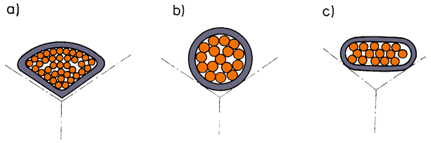
Fig. 4.19. Shapes of multi-core cables : a) sector, b) round, c) oval
Cable
The characteristic feature of cables’ working conductors, apart from the material from which they are made and the way they are made, are their cross-sections.
Nominal cross sections of cable cores are standardized.
The series consists of
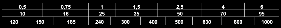 mm2 cross sections.
An insulation of cable cores is a constructional element serving to isolate individual cable conductors from each other and from grounded elements. The insulation of electric power cable cores is usually made of: cable paper supersaturated with electroinsulating impregnant, plastisized polyvinyl chloride (PVC), high pressure insulation cross-linking polyethylene (XLPE) or gum.
A cable sheath is a leakproof layer of a metal or non-metallic material, which protects the cable against migration of humidity to the insulated conductor. Cable sheaths are made of: plastisized polyvinyl chloride (PVC), lead alloys and cross-linking polyethylene.
Armours can be used to protect electric power cables against mechanical damages. An armour of a cable may be made of: steel tapes, round steel wires, profiled steel wires.
A return conductor is a part of a cable used to carry disturbing current. It is coaxially laid on a wire in the core of the cable. This conductor is used in cables made of PVC or polyethylene for voltages higher than 1 kV. The return conductor is made of copper tapes or copper round wires.
An oversheath is a protecting layer or a set of protecting layers in the shape of lappings or braids, protecting the cable against chemical factors and mechanical damages. Oversheats are made of: cable paper, jute yarn, protective saturant, bitumen protective glaze or PVC.
Types of cables
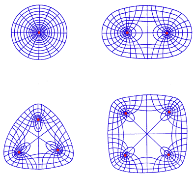
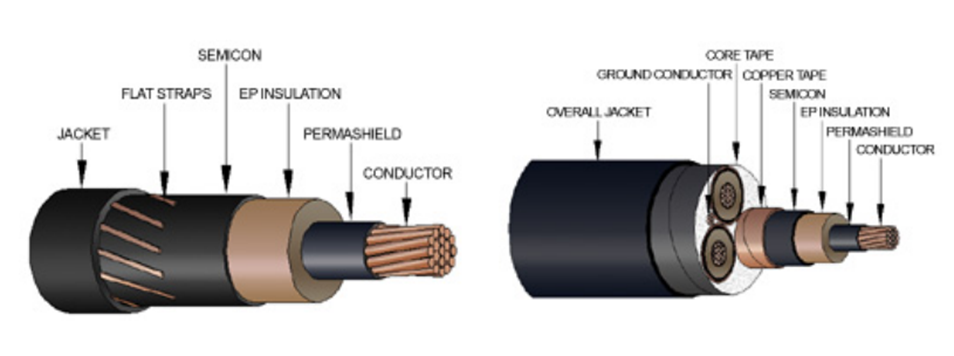
Taking into account the way the insulation is made and the associated distribution of the electric field, there are two main types of cables:
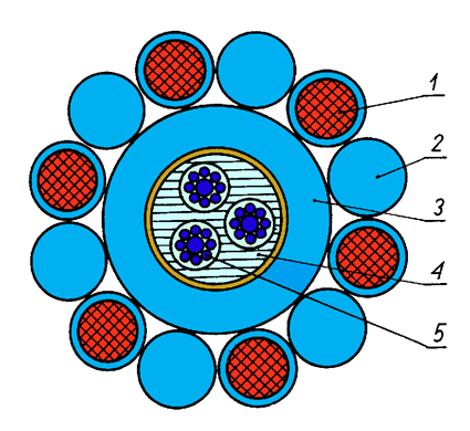
– cables with core insulation (Fig. 4.20) and
– cables with screening conductors (Fig. 4.21).
As it can be seen, the distribution of electric field in cables with core insulation is non-uniform, which can cause breakdowns in the places where field lines are dense.
Kinds of cables
Cables with core insulation have insulation on each working conductor, and additionally so called core insulation laid on all conductors of the cable.
Cables with screened conductors have insulation on each working conductor and a tape of metallized paper laid on insulation. The tapes are metallically connected with each other and with metallic shield of the cable.
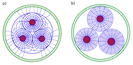
Fig. 4.22. Distribution of electric field:
a) in a cable with core insulation,
b) in a cable with screened conductors
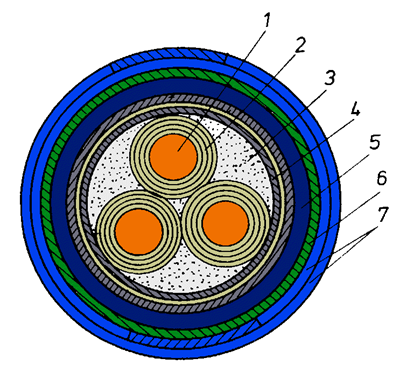
Fig. 4.20. Cable with core insulation:
1 – conducting conductor,
2 – impregnated paper insulation,
3 – centre filling,
4 – core insulation,
5 – lead coating,
6 – fibrous shield,
7 – armour of steel tapes
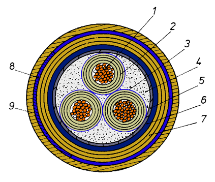
Fig. 4.21. Cable with screened conductors:
1 – conducting core,
2 – impregnated paper insulation,
3 – matallizated paper screen,
4 – centre filling,
5 – gummed tape,
6 – lead coating,
7 – paper-jute layer,
8 – armour of steel tapes,
9 – outer shield of jute
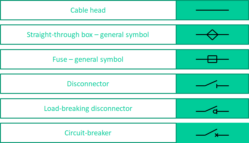
Cable accessories
Cable accessories it is a set of elements used for connection, branching and ending of cables. Cable accessories include: joint boxes, box heads, connectors, terminals, etc.
Cable accessories construction depends on the types of the cables and environmental conditions of their installation locations .
In LV and MV cable networks the following cable accessories are used: indoor and overhead box heads, straight joints, junction joints and transition joints, repair joins and sealing systems, insulated cable adapters, screened connector box heads.
Box head
Box heads are divided into indoor and overhead. They are used to connect the cables to switchgears, transformers and pole insulators.
They are designed for LV or MV cables with plastic insulation or paper insulation (with dripping and non-dripping saturant), single-conductor and multi-conductor cables.
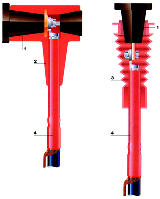
Fig. 4.23. Insulated adapters made by Raychem company:
1 – bushing insulator,
2 – angle adapter of type T,
3 – straight adapter,
4 – heat-shrinkable box head.
Selection of cable
The general term – cable selection – should be understood as the choice of cable structure, cross section of operating and return conductors and the nominal insulation voltage level.
The choice of the cable depends on forecasted exploitation conditions.
The following circumstances must be taken into account when determining the cable route:
– number of junctions and close-ups with other devices and number of crossings through walls, ceilings and other obstacles should be as small as possible,
– guiding of cables through compartments and areas with explosive conditions or with fire hazard should be limited to cables feeding devices in those compartments and zones,
– heat dissipation from the cable to the environment should not be difficult,
– close-ups with heat pipes and cabling along the walls with chimney conduits should be avoided,
– guiding of cables in sunny places should be avoided,
– a cable should not be exposed to mechanical damages and harmful operation of chemicals,
– in the case of cabling in the ground the route should be driven along the streets or through the lawns in belts appointed for this goal,
– back-up cables should be guided in other routes than the basic supply lines.
Cabling in the ground
Cables may be laid directly in the ground, in pipes or blocks situated in the ground. Cables must not be laid in layers, with the exception of cables in industrial plants.
Cabling in ducts and tunnels
Ducts and tunnels for cabling are made of non-flammable materials. Conditions of effective ventilation (natural or artificial) and dewatering of these constructions should be ensured. The details regarding construction of ducts and tunnels are given in special standards and regulations. Cables with a voltage of 40 kV or more and oil cables should be laid in separate ducts and tunnels.
Cabling
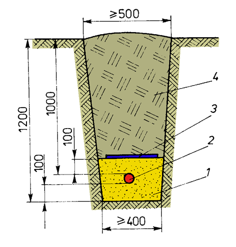
Fig. 4.24. Cross section of a cable trench for a cable of nominal voltage higher than 15 kV :
1 – sand,
2 –cable,
3 – plastic film,
4 –soil.
Construction of electric power substations
Power substations are important elements of the network. Substations are classified according to the nominal voltages of the networks connected by these stations (higher voltage decides):
– extra high voltage substations of voltages 220 kV and higher,
– high voltage substations HV (110 kV),
– medium voltage substations of voltages 6-30 kV.
According to the way of construction, the substations may be divided into:
- indoor substations, in which all equipment is located in the building,
- outdoor substations, having devices installed on special constructions outside a building (Photo. 4.2) and
- mixed, in which some equipment is located in a building, and the other part outside,
- mobile substations used to feed large building sites or temporarily, when permanent substation is built.
Substations
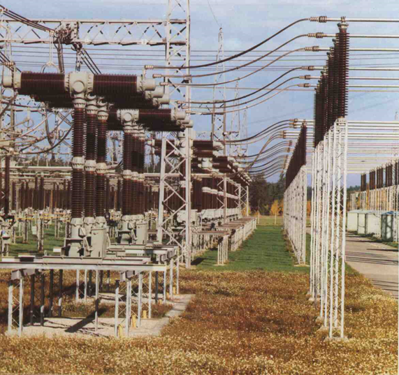 Photo. 4.2. Outdoor 400kV substation
Taking into account the method of insulation, substations are divided into structures with air, solid or gas insulation (SF6) (Photo. 4.3).
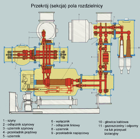
Photo. 4.3. Scheme of a switch-bay of voltage 110kV in hermetic enclosure with insulation SF6
Construction of electric power substations
According to the functions that substations play in the system we distinguish branch fed and through fed substations (Fig. 4.25).
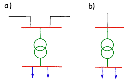
Fig. 4.25. Ways of substation feeding: a – through fed, b – branch fed
Taking into account the function of the substation in the system we distinguish power plant substations and network substations.
Considering the operation of the substation, the substations are divided into: without permanent staff, with one-shift staff, with permanent staff, with daily standby duty, with a central bypass point [visitations] (important substations without permanent service).
Number of transformers fed in the substations influences directly their division. There may be single-transformer substations supplying customers not requiring high reliability of supply, the most frequently used two-transformer substations and multi-transformer substations.
Basic elements of substations
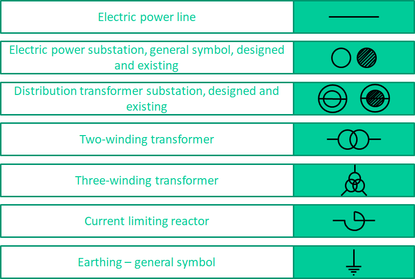
Elements of the main circuits are the basic elements of the substation: transformers, bus bars, insulators, switchgear, current and voltage transformers and current limiting reactors.
In addition, substations may, if necessary, be equipped with the following auxiliary AC and DC equipment:
– devices and installations of secondary circuits,
– devices and installations of compressed air,
– remote control devices,
– communication devices,
– fire-fighting devices,
– lighting devices.
Bays may be equipped with:
– circuit-breakers serving to switch off and switch on short-circuit and working currents,
– disconnectors that ensure obtaining and keeping of secure (visible) insulation break,
– load-breaking disconnectors with fuses – the fuses trip short-circuit currents and the load-breaking disconnectors switch off and switch on working currents (much cheaper than circuit-breakers)
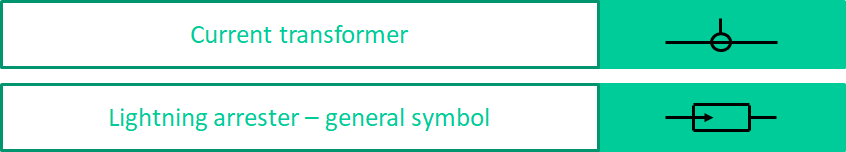
Each type of the bays may be additionally equipped with meters and current transformers.
Feeder bays may be equipped with circuit-breaker, and one to three disconnectors that are installed on both sides of the circuit-breaker. At small powers flowing through the bay (to 800 kVA), the bays may be equipped with load-breaking disconnectors with fuses, which are much cheaper than circuit-breakers.
The bus bars together with the main circuit apparatus and auxiliary equipment form switchyards containing bays, which perform determined functions.
The following types of bays can be distinguished:
– feeder bays (Fig. 4.26a),
– transformer bays (Fig. 4.26b),
– sectioning bays (Fig. 4.26c),
– measuring bays (Fig. 4.26d),
– lightning arrester bays used for the purposes of lightning protection of the substation and equipped with disconnectors and lightning arresters,
– auxiliaries bays serving to feed substation auxiliary transformer.
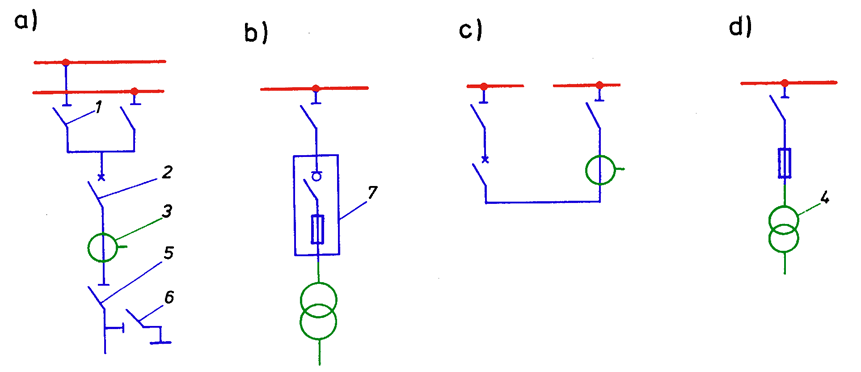
Fig. 4.26. Typical schemes of medium and high voltage switchgears:
a) feeder bay, b) transformer bay, c) coupling bay, d) measuring bay
1 – bar disconnector, 2 – circuit-breaker, 3 – current transformer, 4 – voltage transformer, 5 – line disconnector, 6 – earth switch, 7 – load-breaking disconnector