
9 Power System Protection
Power System Protection
The power system protection (PSP) comprises the electric power protective relays and the switchgear automatics, which have to:
⦁ protect power system elements against the effects of short-circuit overcurrents, operational overcurrents, voltage loss,
⦁ to increase reliability of energy supply.
Protecive relays are the main elements of the power system protection. The relays measure either directly or with the help of current and voltage transformers chosen electric quantities and after eventual overrun of their starting values, they may either signal the fault or switch off the device acting on the final control element, i.e. on circuit breaker.
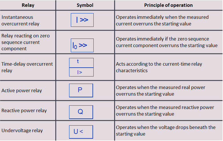
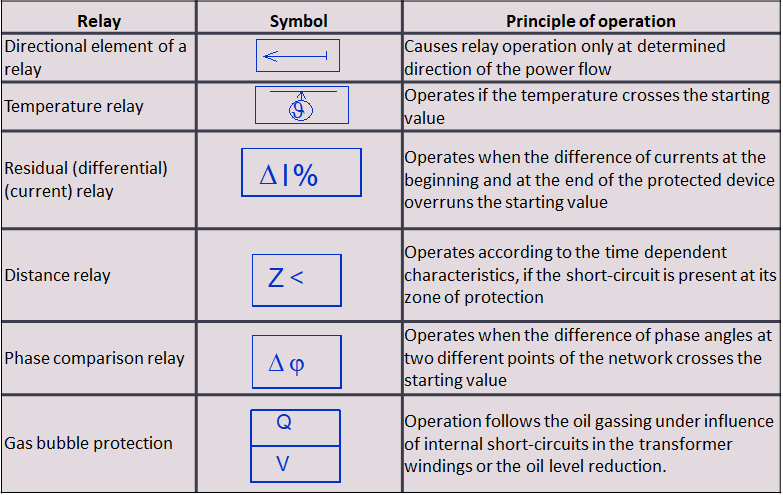
Denotations and principles of operation of basic relays applied in the schemes of the PSP are presented in table 8.1.
Protective devices can be divided into the following functional groups:
⦁ relay protection system – its main objective is to switch off a faulty element,
⦁ automatic reclosing equipment – restores network configuration to the configuration as similar as possible to orginal design,
⦁ preventive power system protection – its objecive is to prevent system malfunction through signaling emergency states, automatic load shedding, switching off, etc.
Those functions are often combined in a single device, which is called the power system protection set.
Protection equipment operational reliability is gained through its redundancy.
Operational selectivity is obtained through the graduation of the operation time of the time-delay protection device, or proper selection of the starting values of the instantaneous protection device.
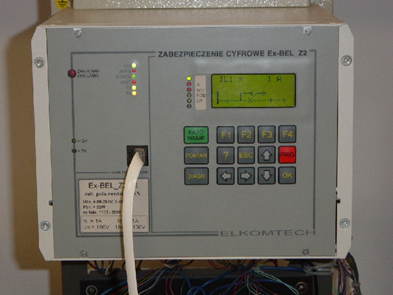
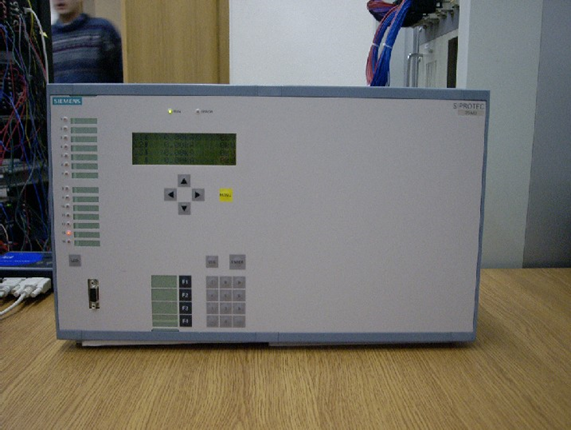
Now, beside still exploited analogous protection equipment, digital protection systems are introduced to the exploitation.
In this lecture we will discuss the basic principles of protection devices operation: electric power lines, transformers, generators and motors.
Power lines
POWER LINES – Preventive and automatic reclosing
The following solutions are applied in electric power networks:
⦁ Automatic stand-by switching-on – When the undervoltage relay detects the loss of supply in the main circuit the back-up supply circuit is closing.
⦁ Automatic reclosing is used in the overhead lines. It recloses the line after its emergency outage, after the time of the current break, suitably selected for the possibilities of the line and circuit breakers, to restore normal work, if the short-circuit is temporary. Twofold automatic reclosing is usually used in the MV networks with the times of the breaks: first 0.5-1 s, second about 10 s. Single-phase and three-phase automatic reclosing is the most frequently applied in HV and EHV lines. Usually it is fast, single reclosing. The automatic reclosing systems cooperate with line protection devices against short-circuits.
⦁ Under-frequency load shedding. It is automatic switching-off the receiving substation, when the deep decrease of frequency exists in the EPS. It corrects the power balance in the power system and increases the frequency, reducing the degree of danger. Loads expected to be switched-off as first are the less important loads in the sense of social losses. Under-frequency load shedding is carried in a few stages, for example: I stage – 48,5 Hz, II – 48 Hz, III – 47,5 Hz, IV – 47 Hz.
⦁ Automatic load restoration (after under-frequency load shedding) has a goal to restore the supply to the receivers after their disconnection by the under-frequency load shedding.
POWER LINES – protection against short-circuits
Protection of MV lines against multi-phase faults
⦁ Instantaneous overcurrent relay is the basic protection device of the line segment. It operates when the current in the line rises above the starting value of the line protection and is installed in two phases. The relay is backed-up by time-delay overcurrent relays with lower starting currents than the instantaneous ones. Those relays enable reserving of protection, because they have low starting current and the time delay adjusted in such a way, that the line segments, when approaching to the supply point, have delays lengthened by Dt = 0,3-0,7 s .
⦁ The protection device cooperate with automatic reclosing systems. Residual (current) protection devices and distance protection devices are also applied in short, important MV line segments.
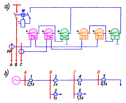
Fig.8.1. Overcurrent protection of power lines:
a) two-phase time-delay and instantaneous protection – principle of operation; b) time graduation in branched radial network (relays 3 and 6 have settings resulting from farther line segments, which haven’t been shown)
I>, I>> – overcurrent relays of time-delay and instantaneous systems; t – time relay; PP – current transformers; W – tripping device of the circuit-breaker
Protection of MV lines against phase-to-earth faults
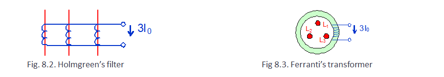
⦁ Protection device reacts on the rise of zero sequence current or power component above the starting value. The zero sequence current can be measured by parallel connection of secondary sides of current transformers in three-phase circuits (Holmgreen’s filter) (Fig.8.2) or by enfolding three-phase circuits by a core of a current transformer (Ferranti’s transformer (Fig. 8.3))
Protection of MV lines against phase-to-earth faults
⦁ The zero sequence voltages may be measured by connection of secondary windings of voltage transformer individual phases in open delta (Fig. 8.4). Relays measuring zero sequence active power component are applied in overhead lines with the insulated neutral; they signal the short-circuit.

Protection of MV lines against phase-to-earth faults
⦁ Relays measuring zero sequence reactive power component are applied in compensated lines; they signal the short-circuit.
⦁ Relays measuring zero sequence current component are used in the networks with neutral grounded through a resistor; they act on switching-off the line with the short-circuit.
Protection of HV and EHV lines
⦁ This part will be limited to the discussion about the most commonly used distance protection systems, sending the persons interested in other kinds of protection to the literature.
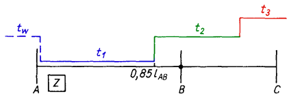
⦁ Distance protection is a protection measuring impedance from a place of short-circuit, it has directional properties and it acts with a delay depending on the distance from the place of short-circuit according to the given impedance-time characteristics (Fig. 8.5).
Protection of HV and EHV lines
⦁ Triggering set of the protection device detect the fault existence, trigger the time set and, after determining the type of fault, trigger corresponding measuring set.
⦁ The measuring element set switch off line:
– in time t1 if the fault is in the first zone having 0,85 of the protected line segment,
– in time t2 for the faults in the II zone, which reaches the half of the shortest line segment outgoing from the substation B (Fig. 8.5)
– in time t3 for the faults in wider the range.
⦁ The protection has usually 3-5 time zones.
Transformers
TRANSFORMER PROTECTION
⦁ Particular role belongs to protection against internal faults in the transformer. In smaller units these are fuses or instantaneous overcurrent protection devices. In the units of power greater than 5 MVA differential protection devices with blocking of its operation under the influence of magnetizing inrush, when the transformer is switched on, is applied. The differential protection device measures current on both sides of the transformer. In case of the fault inside the transformer those currents have different values and this triggers protective device. The protection devices against external faults are, at the same time, back-up protection for lines outgoing from the transformer. Time-delay overcurrent relays or distance relays are used for this purpose in the units with upper voltage 220 kV and 400 kV.
Transformers
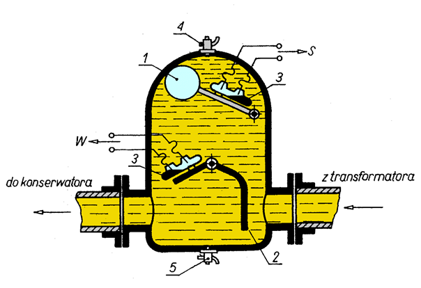
⦁ Gas bubble protection device is installed in the connector between the transformer tank and the oil conservator (Fig. 8.7).
⦁ This relay is triggered in case of winding insulation damage, which cause the oil gassing, or when the level of oil decreases because of the tank leakage.
⦁ Less important damages are only signalised, while at more hazardous situations device switches off the transformer.
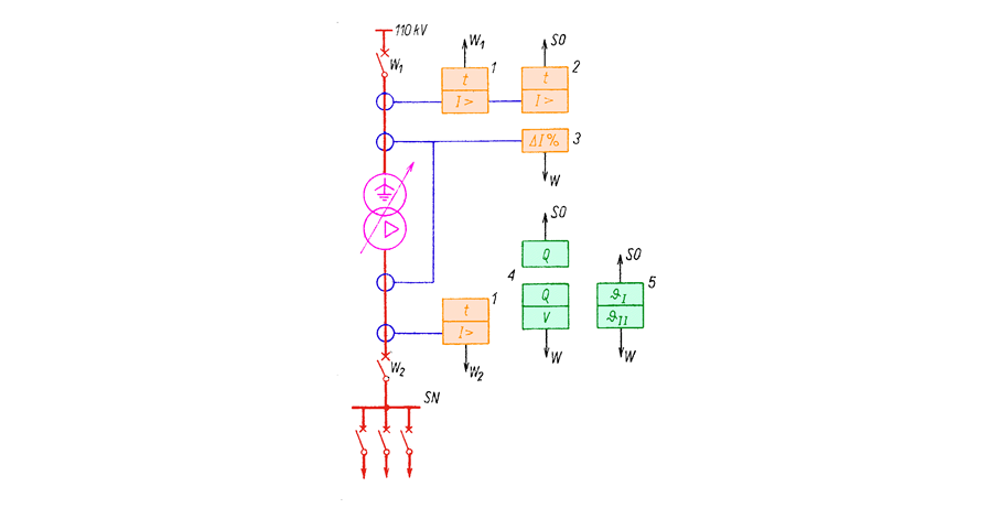
⦁ Autotransformers and transformers with upper voltage 400 kV, 220 kV, should have two sets of basic protection devicess, backing-up each other, transformers with upper voltage less or equal to 110 kV – single set. An example of a transformer protection device has been shown in Fig. 8.8.
Transformers
Generators
GENERATOR PROTECTION
Generator protection devices are adjusted to the generator rated power. Protection devices dedicated to generators (not used for lines or transformers protection) are:
⦁ Protection against the effects of the phase currents asymmetry, reacting on negative sequence current component,
⦁ Protection against single short-circuits in the excitation winding, signaling the faults,
⦁ Protection against double short-circuits in the excitation winding, based on the bridge systems,
⦁ Protection against voltage rise in hydrogenerators, caused by the increase of the rotational speed, realized with the help of the overvoltage relay.
⦁ Protection against excitation loss, which leads to generator asynchronous work with shorted or open excitation circuit, realized by under-impedance protection. It measures internal reactance of the generator, which at asynchronous work is much less than at synchronous operation.
Motors
PROTECTION OF ASYNCHRONOUS MOTORS
Protection devices for motors are adjusted the nominal voltage and the rated power of the asynchronous motor .
⦁ Basic requirement of short-circuit protection devices and overload protection devicses are to not operate during motor start-ups.
⦁ Protection device against voltage reduction (0,6-0,7 Un) should act with long time delay (6-10 s), if the motor is intended for the self-start. Long delay prevents from motor outages during the breaks when automatic reclosing operates.