
8 Short-Circuits in EPS
SHORT-CIRCUITS IN EPS
According to the international standard IEC 609090-8 a short-circuit it is an accidental or purposeful conductive connection between two or more circuit elements, bringing a difference of voltage between those elements to zero or close to zero.
The following short-circuit types are distinguished by the number of possible paths (the phases and the earth) (Fig.7.1):
– three-phase faults and three-line-to-ground faults,
– phase-to-phase faults and two-phase-to-earth faults,
– phase-to-earth faults.
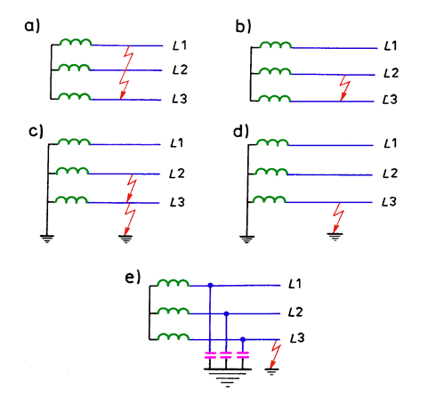
Fig. 7.1. Kinds of short-circuits a) symmetrical three-phase, b) phase-to-phase, c) two-phase-to-earth, d) phase-to-earth in the network directly grounded or through an impedance, e) phase-to-earth in the network with insulated neutral point
In practice, there are also short-circuits, which are a combination of given fault cases. These are multiple faults, i.e. existing at several points in the network.
The lecture will be limited to the discussion of the two types of short-circuits:
⦁ Three-phase-faults far from a generating unit. These are the most frequently calculated faults in the power networks, especially in the distribution networks. They are characterized by the highest currents of all short-circuit types, from a few to several kA and are the basis for the selection of equipment in emergency conditions.
⦁ Phase-to-earth faults in the MV networks with insulated, compensated and grounded neutral point.
REASONS AND EFFECTS OF FAULTS FORMATION
Short-circuits are caused by atmospheric and switching discharges, incorrect switching operation in the power substations, mechanical damages of cables, poles, insulators, wetting or destruction of the insulation, damages of overhead towers, foreign objects on bare conductors, etc.
Short-circuit current in a short-circuit loop is generally (except for phase-to-earth faults in the networks with the insulated and compensated neutral point) many times higher than the current present during usual work of the network devices. This current may cause harmful thermal and dynamic effects in the operation of power equipment.
The phase-to-earth faults in the networks with the insulated neutral point cause formation of currents comparable with the operational currents, from a few to several hundred amperes.
These short circuits can be divided as follows:
– direct (no-arc) faults,
– arc faults with interrupted arc,
– arc faults with persistent arc or nearly persistent arc.
Short-circuits without arc occur when the earth fault current is below a specified limit value. The only unpleasant effect of this type of short-circuit is the increase of voltages in other phases up to phase-to-phase voltages. Such faults usually occur in aerial networks, not very branched.
The arc faults with interrupted arc are much more dangerous for the network. During such faults, transient overvoltages occur in the other phases, which reach a value several times higher than the phase voltage.
The transient overvoltages are not formed if the arc fault is with persistent arc or nearly persistent arc. By the persistent arc is the arc, which although is dumped when the current goes through zero, but the non-current breaks are so short, the they do not cause voltage deformation in the other phases. At the same time there is no current surge at the repeated arc ignition and it is not followed by a sudden rise of the voltage of the shorted phase at the moment of dumping. Short-circuits with persistent arc are formed when the fault current crosses certain limit, which is difficult to be precisely determined.
The arc faults may cause damages of the device insulation, which create the danger of electric shock or the transfer from the phase-to-earth fault to a multi-phase fault.
COMPUTATION OF CURRENTS AT THREE-PHASE FAULT
Equivalent scheme of the fault loop
The international standard IEC 609090-8 introduces equivalent voltage source to the fault loop (Fig. 7.2). The values of the voltage coefficient c are given in table 7.1.
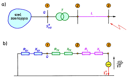
Fig. 7.2. Example of equivalent scheme of the fault loop: a) scheme of the network b) equivalent scheme of the fault loop
Equivalent scheme of the fault loop
TABELA
Table 7.1. Voltage coefficient c
The equivalent source is the only active source in the network. All real sources (feeding lines, synchronous and asynchronous machines) are replaced with their internal impedances. All the network capacitances and admittances connected in shunt to the non-rotating devices are neglected.
Positive sequence component of the fault impedance seen from the place of the short-circuit is being determined for the three-phase fault, which is the most frequently considered in the practice, especially in the distribution networks.
Fault impedances of electric power devices
Equivalent impedance of the power supply is calculated from the formula:
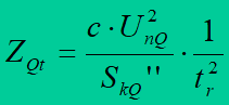
where:
UnQ – nominal voltage of the supply network at the point Q,
SkQ’’ – initial symmetrical short-circuit power at the point Q,
IkQ’’ – initial symmetrical short-circuit current at the place Q,
c – voltage coefficient,
tr – nominal transformer ratio.
Fault impedances of electric power devices
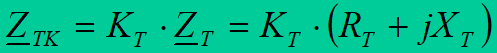
Impedances of transformers, overhead and cable lines and reactors are computed according to the principles presented in lecture about Electric Power Networks.
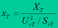
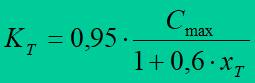
Correction factor KT for transformers is calculated from the formula:
Assumptions for calculation of three-phase faults
The international standard IEC 609090-8 enables determination of short-circuit currents in low, medium and high voltage networks.
According to the mentioned standard the following types of faults are distinguished:
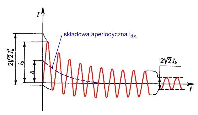
Short-circuits distant from generating units. It is a short-circuit, during which voltage changes causing the short-circuit current flow do not occur and the circuit impedance changes are not significant. The influence of motors is not taken into account. The expected failure current consists of the sum of two components (Fig.7.3):
– symmetrical component with constant amplitude during the fault,
– aperiodic component of initial value A, decaying to zero.
Assumptions for calculation of three-phase faults
The short-circuit fed by one transformer according to Fig 7.3. may be treated as distant from generating units, if:
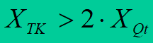
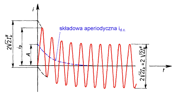
Fig. 7.3. Shape of fault current in a short-circuit distant from generating unit.
Short-circuits close to generating units. It is a short-circuit supplied by at least one synchronous machine with initial symmetrical fault current at least two times higher than the rated current of the machine, or a short-circuit in which asynchronous motors have their share in the initial symmetrical fault current greater than 5%.
The fault current in the fault near a generating unit may be considered as the sum of the two components (Fig. 7.4):
– symmetrical component with the amplitude decreasing during the fault,
– aperiodic component of initial value A, decaying to zero.
7.4. Shape of fault current in a short-circuit near generating unit.
Short circuits in distribution networks can mostly belong to this group. Short circuits in distribution networks of industrial companies that have their own power plants or high engine power.
According to the international standard IEC 609090-8 the two fault currents may be calculated:
Maximal fault current. For the calculation of this current, the configuration of generation sources and networks shall be assumed to give the maximum short-circuit current. The motors are also taken into account and the line resistance at the temperature 20oC is calculated. The maximum current is used to select the parameters of the electrical equipment.
Minimal fault current. For the calculation of this current, the configuration of generation sources and networks shall be assumed to give a minimum short-circuit current. Motors are omitted and conductor resistances are determined from the formula:
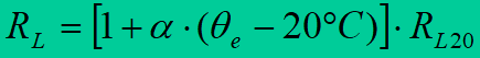
where: RL20 – resistance at the temperature 20 oC,
qe – conductor temperature at the end of the short-circuit,
a – coefficient equal to 0,004 /K.
Minimum current is the basis for selecting fuses, setting up the safety system and checking the starting conditions of the motor.
The calculation of minimum and maximum short-circuit currents is based on the following simplifications:
– number of fault loops does not change during the short circuit,
– transformer tap switches are in their basic position,
– arc impedance is neglected.
Computation of fault currents at three-phase fault remote from generating unit
Initial symmetrical short-circuit current Ik’’ – the effective value of the periodic component of the short-circuit current at the moment of the fault origination; if the impedance sustains its initial value, it is calculated from the formula:
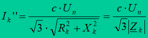
where: ![]() – the voltage of the equivalent source.
– the voltage of the equivalent source.
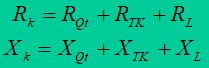
The value of the impedance is :
The resistance may be neglected if Rk<0,3Xk.
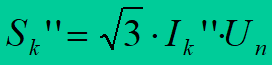
Initial symmetrical fault power Sk” – value defined as the product of the initial symmetrical fault current Ik“, the network nominal voltage Un and the factor √3:
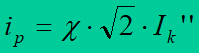
Peak fault current ip (called the surge current according to the old standard) – the maximal possible instantaneous value of the peak short-circuit current, calculated from the formula:
The coefficient c for calculation of the peak short-circuit current is determined (Fig. 7.5) in relation with the ratio Xk/Rk or Rk/Xk .
The coefficient may be also computed from the approximate relation:
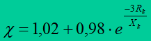
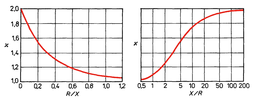
Fig. 7.5. Dependence of c coefficient on the ratio Rk/Xk and Xk/Rk
Symmetrical breaking short-circuit current Ib – the effective value of one complete cycle of the periodic component of the fault current at the moment of separation of the contacts of the first switching pole, determined on the basis of the formula:
Sustained short-circuit current Ik – the effective value of the fault current, after the end of transient phenomena, equal to:
Equivalent thermal fault current Ith – the effective value of the current, which causes the same thermal effect and lasts as long as the real fault current and which may contain aperiodic component and may decrease during the time, determined by the formula:
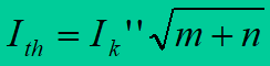
where: m – a coefficient regarding thermal influence of the fault current aperiodic component, n – a coefficient regarding thermal influence of the fault current symmetrical component. The values of the coefficients m and n are read off from the graph in Fig. 7.6. and Fig. 7.7.
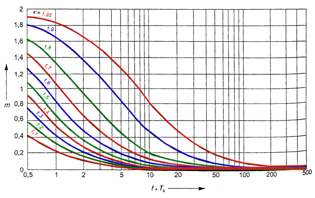
Fig. 7.6. Relation between coefficient m, determining thermal effect of fault current aperiodic component and short-circuit duration
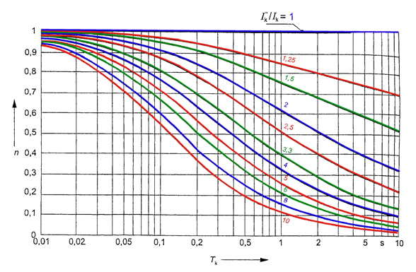
Fig. 7.7. Relation between coefficient n, determining thermal effect of fault current symmetrical component and short-circuit duration
The coefficient c is read off from the graph in Fig. 7.5. n = 1 is usually assumed for a distribution network.
SINGLE-PHASE-TO-EARTH FAULTS IN MV NETWORKS
Network with insulated neutral point
Some segments of overhead medium voltage networks work with an insulated neutral point. A loop of short-circuit current, in case of a single-phase-to-earth fault, is closed through shunt admittances of a line. Those admittances are constituted
mainly by capacitive shunt reactance of the line
(Fig. 7.8).
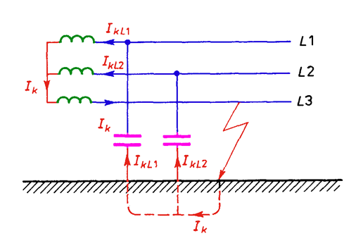
Fig. 7.8. Example of a short-circuit current
Series reactances of the line and transformer windings are very small in comparison with the capacitive shunt reactance of the line and they may be neglected. In the network with insulated neutral point earth fault current has nearly capacitive character. Phase-to-earth capacitance decides about the value of that current.
In direct short-circuit in calculations, the fault current will be equal to:
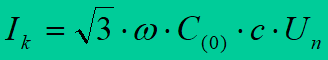
where: C(0) is a capacitance for a zero sequence component of a single phase of the line.
During the earth-fault in the network with insulated neutral point voltages in other phases rise to the values of phase-to-phase voltages (Fig. 7.9). A voltage of the neutral point of this system increases, in relation with the earth, from zero to the value of a phase voltage.
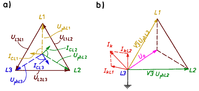
Fig. 7.9. Phasor diagrams of voltages.
To calculate earth fault current in the network, a set of galvanically connected MV lines should be separated (Fig. 7.10). That set is formed by lines fed from one 110/MV transformer winding.
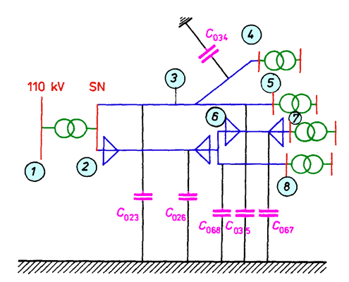
Fig. 7.10. Example of MV network.
Compensated network
A capacitive earth current may be compensated by an inductive current (Fig. 7.11).
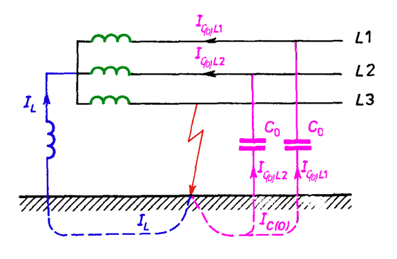
Fig. 7.11. Scheme of compensation
Transformers 110kV/MV in the Polish electric power network have connection group Yd. Because of that reactors are connected to the MV network through grounding transformers with the connection group Zy (Fig.7.12). Those transformers are, at the same time, used to supply auxiliary devices in 110 kV/MV substations.
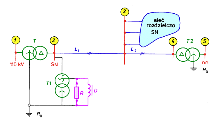
Fig. 7.12. Typical for domestic conditions network layout with neutral point of MV network grounded through resistor R or compensation reactor D
Earthing transformer impedance for zero sequence component Z(0)Tu and reactor impedance jwLpu should be considered in the impedance of the neutral point Zpu
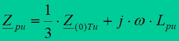
Fault current is determined by the formula:
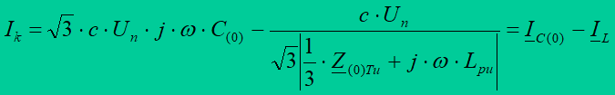
Total compensation is not possible in practice, because a current in a short-circuit loop is not a pure capacitive current, similarly like compensation current is not purely inductive current. The sum of vectors of the current flowing through line capacitances IC(0) and the compensation current IL is called residual current Iresztk . (Fig. 7.13)
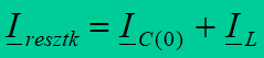
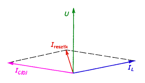
Fig. 7.13. Phasor diagram of currents
Network with neutral point earthed through resistor
Earthing of neutral point through resistance RN is a solution especially preferred in MV cable networks. It enables fast tripping of phase-to-earth faults by suitably selected protection devices. Precise determination of phase-to-earth short-circuit currents with neutral point grounded through resistance requires complicated calculations. For a direct short-circuit it may be calculated from the approximate formula:
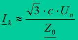
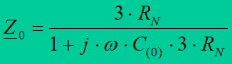
where: RN – grounding resistance.
METHODS OF FAULT CURRENTS EFFECTS LIMITATION
Effects of short-circuit currents
The highest short-circuit currents reaching several, and often even several dozen kA usually occur at three-phase short circuits. These currents, despite their short duration, cause significant heating up of devices leading to insulation damage and even insulation fusion. They cause high electrodynamic forces leading to mechanical damage of network devices. Short-circuits cause voltage drop and interference in the operation of other receivers. Rapid changes in the load of generators can causetheir falling-out of synchronism.
Single-phase-to-earth faults in MV networks with insulated or compensated neutral do not cause flows of high currents, so they do not cause dangerous thermal or dynamic effects. However, they create transient and permanent overvoltages, which can be dangerous for the insulation of the equipment. They also create a risk of electric shock and may lead to the damages to components such as reinforced concrete poles.
Proper selection of network configuration
Splitting of a network into segments fed from different sources is the basic method of short-circuit powers and currents level limitation (Fig. 7.14)
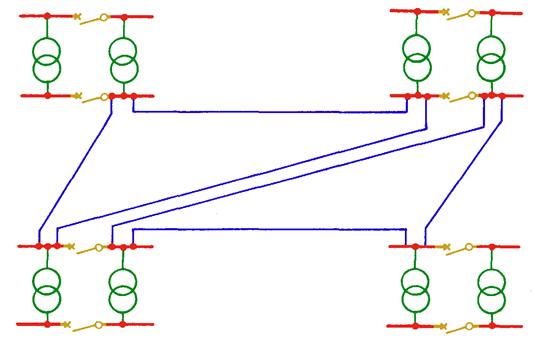
Fig. 7.14. Splitting of 110kV network into segments
Effects of short-circuit currents
It is assumed that each short-circuit current source (generator, transformer, feeder) operate on separate bus section. Separating of networks supplied from two or more sides is also applied, for example by the disconnection of one or a few feeders.
Splitting of a network and avoidance of parallel work of transformers may be not enough measures for sufficient limiting of short-circuit currents in very expanded networks.
Short-circuit transformers and current limiting reactors
Installation of transformers with higher nominal powers (110kV/MV transformers of powers 31.5 MVA and higher) requires the usage of additional devices, which limit short-circuit currents in the MV network, for example current limiting reactors or transformers with increased short-circuit voltage.
Impedances of transformers have essential influence on the value of fault currents. Short-circuit currents on the secondary side of the transformer may be limited by increasing the short-circuit voltage and at the same time its reactance. Two-winding and three-winding (separated windings transformers) 110/MV transformers with the short-circuit voltage increased to 18% are applied in Poland. The short-circuit voltage in a normal transformer is either 10,5% or 11%.
Short-circuit transformers and current limiting reactors
Feeder reactors are installed, in general, on the outgoing lines from substations.
According to the requirements:
– switchgears with a part of outgoing feeders equipped with reactors (Fig. 7.15) are applied when limitation of short-circuit currents in all the outgoing lines is not necessary.
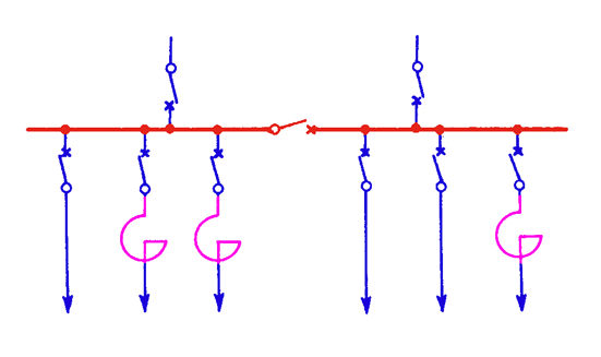
Fig. 7.15. Current limiting reactors on a part of outgoing feeders
– switchgears with group reactors (Fig. 7.16.) used, when there is greater number of outgoing feeders of lower power, and the reliability requirements are not very strict,
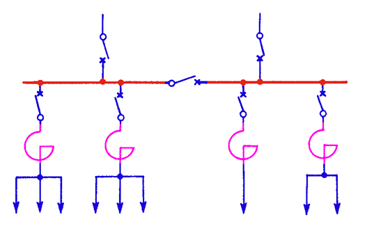
Fig. 7.16. Current limiting reactors on groups of outgoing feeders
– switchgears with reactors on all the outgoing feeders (Fig.7.17) are applied at considerable short-circuit power and in short cable lines. This solution prevents the decrease of voltage on the bus-bars when the short-circuit is behind the reactors.
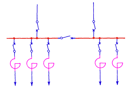
Fig. 7.17. Current limiting reactors on all the outgoing feeders
Considerable voltage losses on the windings, in normal conditions of work, are the most important disadvantages of all reactors.
That is why the reactors are not installed in newly built MV substations. They have been replaced by the transformers with increased short-circuit voltage. Nevertheless the current limiting reactors are often met in older MV substations.
Other technical solutions used to limit the short-circuit currents are:
⦁ reactors with magnetized ferromagnetic core,
⦁ resonant coupling.
Grounding of 110kV transformer neutral through a resistor in MV networks, causes removal of negative phase-to-earth short-circuit current effects because the line, in which the fault exists, is tripped very quickly.