
11 Protection against electric shock (fin)
The goal of the laboratory task is to get the basic knolegde about electric shock, which may take place in common AC earthning arrangements. Investigations includes testing the basic protection devices.
1. General information
The use of electrical devices cause a certain electric shock hazard. To reduce the effects of its happening some counteractions can be taken. During the normal and fault operation conditions we can distinguish type of voltage such as:
operating voltage – voltage between conducting parts of electrical and the ground or phase to phase voltage,
nominal (rated) voltage – voltage that the network and electrical devices installed in this network was design for,
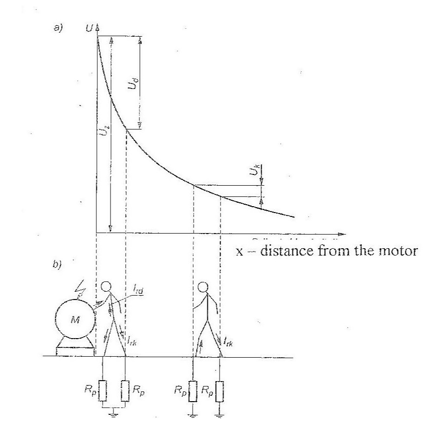
touch voltage – voltage between chase of the electrical device and the ground,
step voltage – voltage between two points on the surface of the ground in the distance of 1 mfrom each other.
safety touch voltage – is the highest permissible value of a touch voltage which may occur for the long time. Table 1 presents values of safety voltages in AC and DC conditions
| Enviromental conditions | Alternating current | Direct Current |
| normal | 50 V | 120 V |
| particular | 25 V | 60 V |
Protection against electric shock must be provided by appropriate technical solutions in the entire installation, in its part or only in one device, can be ensured by:
1) basic protection under normal operating conditions and in conditions of single damage – fault protection.
2) by a reinforced protection measure that provides protection both under normal operating conditions and under single fault conditions.
1.1 Basic Protection
The following basic protection measures are distinguished in the protection against electric shock:
– basic insulation of active parts,
– housing,
– obstacles (fences),
– placing out of reach of the hand.
1.2 Fault Protection
The following faultprotection measures are available for general use:
1) automatic disconnection of supply,
2) double insulation, protective insulation cover,
3) galvanic separation,
4) savety extra low voltage.
1.2.1 Automatic disconnection of supply
The protection measure by automatic disconnection of supply should switch off one or more power lines of the device or installations in case of damage to the basic insulation in the required time. It is realized by overcurrent switches of fuses. The required time is presented in table 2.
| Network arrangement | 50 V ≤ U ≤120 | 120 V < Uo ≤ 230 | 230 V < Uo ≤ 400 V | 400 < Uo | ||||
| AC | DC | AC | DC | AC | DC | AC | DC | |
| TN | 0,8 | – | 0,4 | 1 | 0,2 | 0,4 | 0,1 | 0,1 |
| IT | 0,3 | – | 0,2 | 0,4 | 0,07 | 0,2 | 0,04 | 0,1 |
1.3 Additional protection
Additional protection for basic protection consists in installing in the protected circuit a high-sensitivity residual current device with a differential current IΔn often set to trigger value 30 mA.
Addtional protection for should be applied:
a) in circuits of general public socket outlets, with a rated current not exceeding 20 A, intended for use by unqualified personel (bystanders),
b) for the protection of mobile devices with a rated current not exceeding 32 A, intended for outdoor use,
c) to protect devices used in conditions of particular danger.
Residual current device is design measure the geometric sum of currents flowing in phase lines and neutral line. When the sum is not equal to zero (leakage current is detected) then circuit should be disconnected. RCD can be installed only when PEN wire is not used. Figure 3 presents differencial current – time characteristic of triggering RCD device

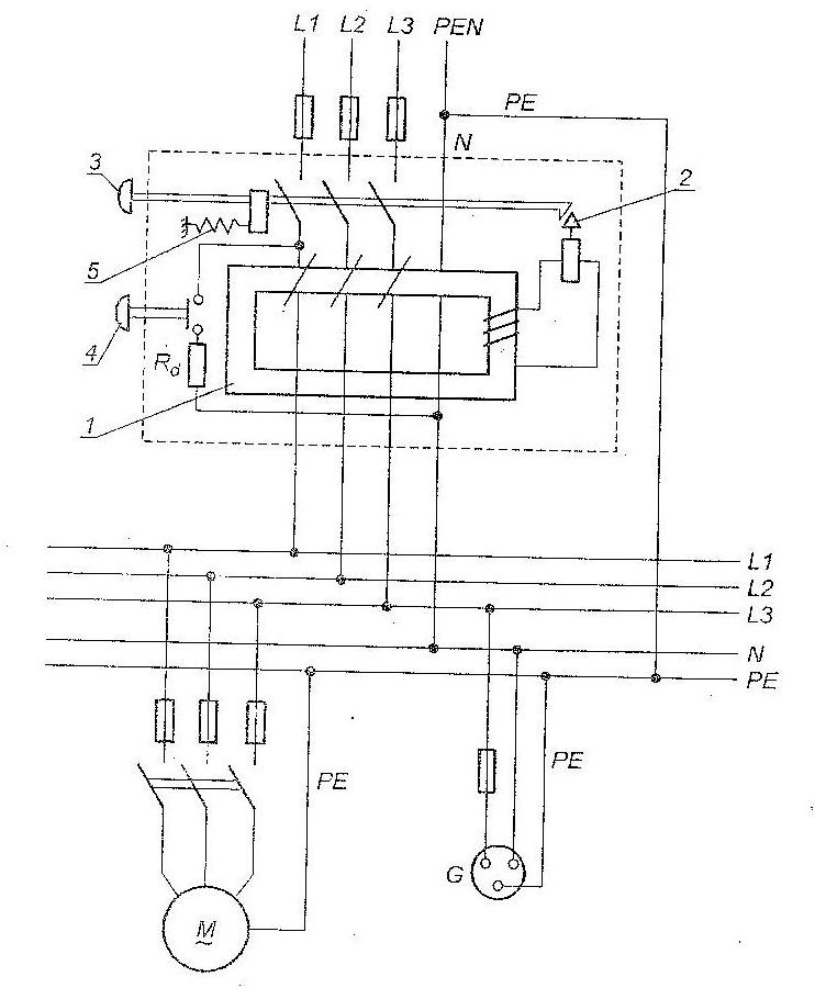
2. Network arrenments
The first letter indicates the connection between earth and the power-supply equipment (generator or transformer):
- “T” — Direct connection of a point with earth,
- “I” — No point is connected with earth.
The second letter indicates the connection between earth or network and the electrical device being supplied:
- “T” — Earth connection is by a local direct connection to earth,
- “N” — the neutral connection is supplied by the electricity supply network, either separately to the protective earth wire (TN-S) or combined with the protective earth (PEN) wire (TN-C).
3. Laboratory Stand
The laboratory front panel is presented in the figure
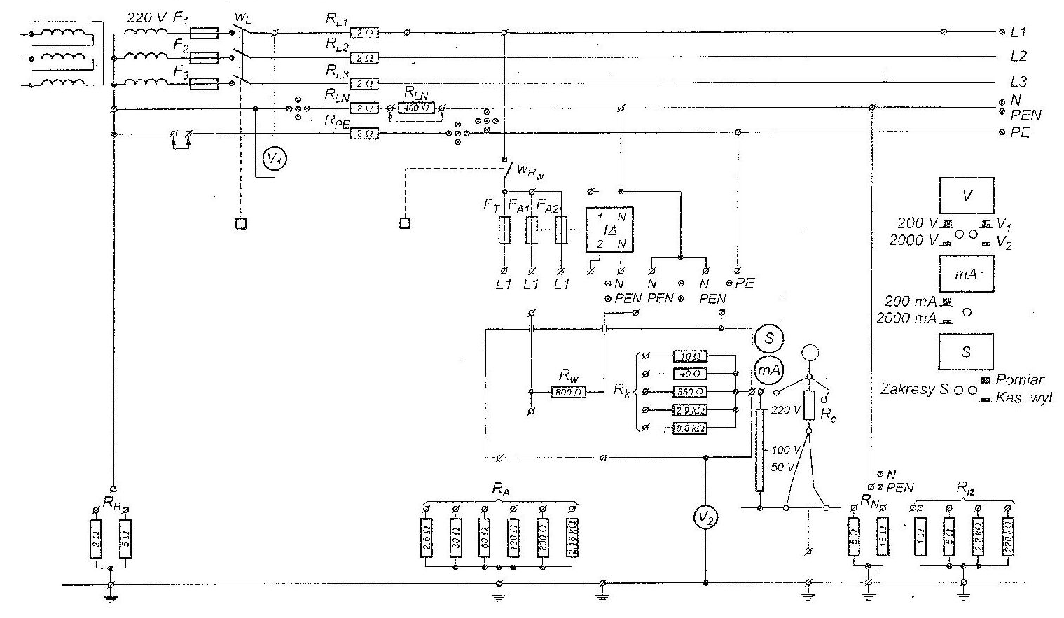
The model consists of the following real elements related to the alternating 220 V voltage:
– 220/22 V feeding transformer,
– auto-transformer.
– RL resistors modelling line resistance,
– RLN resistor modelling the resistance ofa neutral PEN conductor,
– RPE resistor modelling the resistance ofa PE conductor,
– RW resistor modelling internal receiver resistance.
– RK resistors modelling insulation ofreceiver resistance,
– RB resistors modelling the resistance ofa neutral transformer point grounding,
– RA resistors modelling the resistance of protective grounding,
– Riz resistors modelling the resistance of network insulation,
– RC resistor modelling the resistance ofa man,
– RN resistors modelling the resistance of additional grounding of network neutral conduc-
tor PEN,
– digital voltmeter,
– digital miliammeter.
– stop-watch with digital reading,
– system signalling touch voltage (light line),
over-current switches R41 and Rig,
differential current switch IΔn = 30 mA.
The detailed program of the laboratory classes is presented in the protocol given to students.
The report should contain the scheme of the investigated network in which there should be marked the type and place of fault, the path of short-circuit current flow and shock current flow. On the bases of the knowledge of modelled resistance values for one ofthe tests, there should be calculated the resistance of the shon-circuit loop_ the value ofthe short-circuit
current, shock current and the touch voltage, Calculated results should be compared with the results from measurements, On the bases of measurements of over-current and differential current protective device operating times should he stated if these devices operate correctly and fulfil the requirements of the standard PN-IEC 60364-4-41, Draw conclusions from the
cases when they maloperate that means they do not fulfil the requirements ofthe existing
standard PN-HEC 60364-4-41.